• The move to the new server is done. There are some software and database maintenance updates in process. This has us passing the hat around to help out. We appreciate any donations. Seriously, even a dollar helps. The payment page may be found here - https://www.audiokarma.org/support.html

My first idler TT and restoration. Building a plinth, damping, tonearm board etc. starting with mint

ve7kilohertz

Active Member
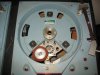
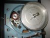
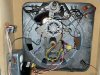
I have just decided to get back into vinyl playback and wanted to try an idler table as I already have an SP-10MKII, SP15, Oracle Delphi MKIII and a few other Japanese DD TTs, an idler just seemed like the next thing to have in my system. I have been reading about them for the last few weeks and started calling a few of my audio friends and one of them had a pair of Russcos in his collection that he was ready to part with. It's ironic that in my ham radio days I used to go around stations in the northwest US and BC looking for old transmitters and ended up hauling home a lot of the stuff the engineers had stored in the transmitter buildings, consoles, R-R decks and TTs. It's entirely possible I donated these to the radio museum I belonged to in the 90's, and here they are back at my house. Too funny. :rolleyes:

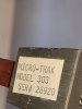
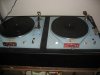
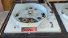
They are Russco Studio Pro model B, in near mint condition and have been well maintained over the years, consecutive serial numbers which is very cool, and still the original platters with matching serial numbers. They came with Micro Trak 303 arms on a minimal base and some odd wiring underneath. My plan is to separate them and build individual plinths, arm boards and maybe even mount an arm separate from the chassis. From what I can see there is a lot of room for improvement from the original commercial design, chassis damping, motor suspension etc. This will be a bit of a project as I don't currently have my woodworking shop setup but will this spring.

I'll be looking for some guidance from those of you who have upgraded these types of tables, damping ideas, suspension upgrades, plinth design etc.

This post is just to get the thread rolling, more pictures will follow as I start the dismantling.

Look forward to hearing about things I can do to upgrade these for home use.

Cheers


IMG_3238.JPG

IMG_3230.JPG

IMG_3235.JPG
 
Register to hide this ad
These make great tables when restored/reworked. Look for a post started by @adnick on his epic plinth build he did for my Studio Pro. More than just a plinth build it documents the work done to whip our tables in shape.
Andy is our resident idler expert and has restored/hot rodded a number of idlers.
I see your missing one of the lamps, be very careful wlith them, they are like hens teeth.

BillWojo
 
Thank you Bill,

I think I saw that thread a while ago in my search for info. I will find it again and read it all, I think I made it to page 2 or 3. The pictures I posted were taken by my friend and I think that was a flash artifact that made the light disappear, I just looked and all lamps are actually there. :banana: One deck had an issue which is the idler shaft assembly casting broke during a move sometime in it's history, it has been repaired with a patch plate but I may revisit it and weld it back together, that is still to be determined.

My current plan (subject to change without notice) is to restore one to a completely original look but with under deck improvements, the other I would like to modernize its appearance, maybe a colored powder coat, or hammertone finish or??...still lots of time to decide. I have never built a plinth but have plenty off woodworking experience so I need to figure out a design and again, I might try two radically different ones. I have researched Delignet's Panzerholz and it seems to be very hard to acquire, I'm sure there are other suitable materials which are more readily available. They also make other similar materials which may be easier to source, FRCW, Multiplex and a few I can't recall. And there is also Baltic birch which I should be able to find locally.

I'll post some better pics later today when I get a moment.

Thanks for your help.

Cheers

IMG_3835.JPG
 
Last edited:
Congrats on your good fortune :thumbsup:

Bill is a good friend (@BillWojo) and he tends to be overly kind and modest;) he came up with a huge modification that can be implemented by some creative thinking even if your not a machinist.

Besides all the obvious and talked about maintenance/modifications and plinth design aspects, reducing motor voltage and cleaning up the electrical input will reduce motor noise/vibration.

Both Bill’s table and Steve’s (@musiqlovr) have been stripped and powder coated, they look fantastic, mine is just the black speckled version….

Duane (@MisterDK) has a rebuild in stock form that looks great, in fact he had the same broken part, and implemented a creative solution, plus there’s several others…

Looking forward to your project,

Andy
 
Thanks boys, appreciate the warm welcome.

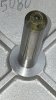
Here are a few more pictures, I can see a little spindle maintenance is in order. Also going to remove the "ham" mods for remote start/stop.

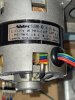
I just finished helping my friend setup his Garrard external power supply made by CTS, variable voltage and frequency, I may make a DIY version of the same, a nice clean sine wave generator, or maybe I'll just filter the crap out of the line voltage. The motor label indicates 115VAC, is there a need to be lower than this? My line voltage hovers around 117 into the house and 115 at the audio equipment outlet.

I'll check out the suggested table threads and garner some more knowledge, lots to learn.

Cheers

PS let me know if I am uploading too many pics.

IMG_4331.JPEG

IMG_4332.JPEG

IMG_4333.JPEG

IMG_4334.JPG

IMG_4335.JPG

IMG_4336.JPEG

IMG_4339.jpeg

IMG_4341.jpeg
 
Thanks Duane,

I just found your 5 page thread and am working my way thru it, seems like there is a good hard core group of Russco guys on this forum, very cool.

I'm going to read thru as much as I can so I can avoid any mistakes, like using the wrong solvents to clean the bearings etc. :dunno:

Here we go, keep your hands inside of the car at all times.

Cheers

Paul
 
Last edited:
I need to get these off the floor and give them a good going thru, I just discovered that all the speed lights have been changed to new ones, heat shrink on the wires underneath, and no speed indications. Shoot, now I need to find 33/45 speed lights, or lenses to make this original.

I also discovered the warranty tag underneath, it expired Dec. 10, 1982, not sure what the warranty period was but I imagine this would make them built around 1981?

Duane what is the s/n of your unit or do you know the date it was built? My spindle ball bearing is at the bottom of the well, not on the spindle shaft.

Cheers

IMG_4352.jpeg
 
I need to get these off the floor and give them a good going thru, I just discovered that all the speed lights have been changed to new ones, heat shrink on the wires underneath, and no speed indications. Shoot, now I need to find 33/45 speed lights, or lenses to make this original.

I also discovered the warranty tag underneath, it expired Dec. 10, 1982, not sure what the warranty period was but I imagine this would make them built around 1981?

Duane what is the s/n of your unit or do you know the date it was built? My spindle ball bearing is at the bottom of the well, not on the spindle shaft.

Cheers

View attachment 2829340

I don’t recall ever looking for a serial # on mine, but always assumed it’s from mid to late ‘70s. Mine uses the Bodine motor but with the turned down armature shaft instead of the earlier, removable capstan - so this motor is probably just before the Japanese Nidec motor was used.
The separate platter spindle bearing is also later than the pressed one - thankfully, Bill gave me one of his Delrin modified thrusts, so this should last a good, long while before worrying about that bearing. Those pot-metal idler arms aren’t the last version though - Andy’s uses the last version steel type. If you’d like to try a really nice one, Serge in Ukraine (if he’s still able), makes very nice ones of solid brass..
 
Cool! Thanks Duane.

My s/ns were on tags on the chassis under the platter, and the platters were engraved with it as well. I just learned more from your 5 pg thread and looked at the weights (bottom side) on my tone arms and sure enough, the stickers are there, and consecutive serial numbers just like the tables. Wow! All original as they came from the dealer. Funny, I was told the only way to adjust these tonearms for different cartridge weight is to use different brass shims under the cartridge, now we know. ;)

So does my spindle bearing need updating or is mine the "good version"?

In my shop I have 2 milling machines and 2 lathes so I am looking forward to hot rodding some of the parts on these TTs when the time comes. I also have to dig out all my woodwork equipment as I don't like to have wood dust in the metal shop. Spring is coming so I can setup once I get access to the storage building (snow melts).

Cheers

IMG_4354.jpeg

IMG_4363.jpeg
 
Cool! Thanks Duane.

My s/ns were on tags on the chassis under the platter, and the platters were engraved with it as well. I just learned more from your 5 pg thread and looked at the weights (bottom side) on my tone arms and sure enough, the stickers are there, and consecutive serial numbers just like the tables. Wow! All original as they came from the dealer. Funny, I was told the only way to adjust these tonearms for different cartridge weight is to use different brass shims under the cartridge, now we know. ;)

So does my spindle bearing need updating or is mine the "good version"?

In my shop I have 2 milling machines and 2 lathes so I am looking forward to hot rodding some of the parts on these TTs when the time comes. I also have to dig out all my woodwork equipment as I don't like to have wood dust in the metal shop. Spring is coming so I can setup once I get access to the storage building (snow melts).

Cheers

View attachment 2829361

View attachment 2829362
Mine has/had the same spindle, grub screw combo as yours, based on my experience doing a modification like Bill did, replacing the ball with Delrin pad, greatly reduced transferred table noise to the tonearm. You can read more about it in my plinth build thread….

Andy
 
Mine has/had the same spindle, grub screw combo as yours, based on my experience doing a modification like Bill did, replacing the ball with Delrin pad, greatly reduced transferred table noise to the tonearm. You can read more about it in my plinth build thread….

Andy

Darn… Now I’ll have to pull the Russco back out to make proper feet and pretty up the box (plinth).. And I had other projects to concentrate on.. :confused:
 
Duane:

Sounds like me, I’ll completely finish a work for someone else, going overboard more often than not :cool:

However there’s always something left to do on my own projects;)
 
I just had to do it.... "It's his bling" from the Transformers movie. 5 minutes on the buffing wheel. For some reason I'm thinking this TT might get bright red powder coating, milled natural pallet wood for the sides on top of the "structure", should look good with the chrome like ring of the platter and a black mat.

Cheers

IMG_4368.JPG
 
Well I am part way thru all of your build threads but haven't come across any mention of damping the underside of the platter. I would imagine a nice even layer of Dynamat or similar would go a long way to eliminate the ringing of the platter. Also, it may benefit the chassis to have some Dynamat attached to various flat locations. Just thinking out loud.

As for the Delrin idler, could I machine one on the lathe then put a groove in the outside and run an o-ring or square belt around the perimeter? I have a shoebox full of brand new oil-lite bushings of various sizes, hopefully one that would fit the idler arm. I'll have to get out the micrometer and measure it, as well as find the box of bushings. :rolleyes:

Back to more reading and smoking (bacon) on the smoker. It's almost happy hour too. :beerchug:

Cheers
 
Well I am part way thru all of your build threads but haven't come across any mention of damping the underside of the platter. I would imagine a nice even layer of Dynamat or similar would go a long way to eliminate the ringing of the platter. Also, it may benefit the chassis to have some Dynamat attached to various flat locations. Just thinking out loud.

As for the Delrin idler, could I machine one on the lathe then put a groove in the outside and run an o-ring or square belt around the perimeter? I have a shoebox full of brand new oil-lite bushings of various sizes, hopefully one that would fit the idler arm. I'll have to get out the micrometer and measure it, as well as find the box of bushings. :rolleyes:

Back to more reading and smoking (bacon) on the smoker. It's almost happy hour too. :beerchug:

Cheers

While Dynamat would work well, you may need to raise the platter height so that there’s clearance for the idler arm stud - just a thought.
You can try sticking some clay underneath, replacing the platter with clay over the stud and then checking the thickness to determine clearance, before adding any damping material.
Put the speed lever in 33 rpm before doing this as it will raise the arm and idler wheel up to the top, getting it close to the platter underside.
Platter is easily raised by screwing in the grub screw (setscrew) at the bottom of the platter bearing well - you’ll need to loosen the jam-nut first.. ;)
My platter does ring and some damping surely wouldn’t hurt..
 
Well I am part way thru all of your build threads but haven't come across any mention of damping the underside of the platter. I would imagine a nice even layer of Dynamat or similar would go a long way to eliminate the ringing of the platter.

Anything you do, you don't want to disturb the dynamic balance of the platter.

I would suggest doing as we Lencophiles do - stack a platter on top of another, placing a suitable mat between them, like a sandwich. Since (good) platters are dynamically balanced, the system will still be balanced as long as the top platter is well centered.

The mass of the top platter over the mat over the bottom platter cancels out the platter resonances.
 
While Dynamat would work well, you may need to raise the platter height so that there’s clearance for the idler arm stud - just a thought.
You can try sticking some clay underneath, replacing the platter with clay over the stud and then checking the thickness to determine clearance, before adding any damping material.

Ok that sounds like a good plan, maybe just between the 4 webs just out from the spindle would be enough.

So while I was enjoying happy hour sitting on my bulldozer watching the sun go down, I had a few thoughts. For the idler arm, if I am building one from scratch, I wonder how a bearing would work vs a bronze bushing, for one or both sides of the idler arm. I haven't looked at the chassis side of it so maybe that wouldn't work, but for the Delrin idler? My guess is the bearing will be noisier than the bushing but I just thought I would throw it out there. The other thing I was wondering about, how about CLD (constrained layer damping) but in the vertical plane instead of the usual horizontal? Make a nice box with vertical sides then a layer of damping then more wood? It would save a lot of futzing around with router and jigsaw on multiple pieces...again just my crazy ideas while letting the brain relax.

Cheers
 
Last edited:
Ok that sounds like a good plan, maybe just between the 4 webs just out from the spindle would be enough.

You can search ebay, they already sell spindle extenders (mostly intended to be used with Lencos but they can be used with other TTs), they allow one to stack a lenco platter on top; there are others that allow you to stack one or even two Rega glass platters on top. Your choice!! A glass platter can be a great idea really.
 
You can dampen the platter with a good mat and there’s room for a large o ring in the platter indentation on the outer rim, don’t believe one needs to add anything underneath the platter.

Vertical is an option but it will change dampening & frequency or noise transference; you’ll create a different path with the ends turned towards the “generator” table.

Without testing with the target table I’m not sure how well it will work. I’ve considered using modeling clay to make an indentation type model for the sub platter internals, something like a covering of Seran Wrap would help….Of course a compartmented plinth filled with something (sand is one option) is another option.

Plinth building and opinions on same, is a deep dark well ;)
 
Back
Top Bottom