• The move to the new server is done. There are some software and database maintenance updates in process. This has us passing the hat around to help out. We appreciate any donations. Seriously, even a dollar helps. The payment page may be found here - https://www.audiokarma.org/support.html

My McIntosh plunge

Before doing any more work on the C26 I decided to set up an A/B comparison with an external phono stage. My goal here is to create an external standard, or yardstick, so that I can judge whether future modifications have any significant effect on the sound.

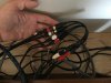
Briefly, I split the signal from the turntable and sent it to two separate preamps.
IMG_5757.JPG

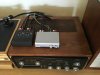
One path now goes to the C26 phono 1 input while the other goes into a Pro-Ject Phono Box. The outputs of the C26 and the Phono Box are both connected to a Schiit passive preamp: basically a switch with an attenuator.
IMG_8553.JPG

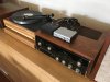
The output of the Schiit (which is one of my favorite pieces of audio gear ever) goes straight into the MC2120 power amplifier.
IMG_9906.JPG

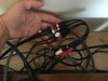
The gain of the Phono Box is much lower than the maximum gain of the C26, so I can set the volume on the McIntosh to exactly match the output of the external phono stage. In this configuration the attenuator on the Schiit controls the master volume and the switch allows seamless comparison of the McIntosh and Pro-Ject phono stages.
IMG_3950.JPG

After a little bit of listening, I can say that there is not much difference between the Pro-Ject box and the McIntosh. I can hear some subtle differences but I need to do more listening to see what I really think.
 

Attachments

  • IMG_4376.JPG
    IMG_4376.JPG
    74.3 KB · Views: 7
Last edited:
Briefly, I split the signal from the turntable and sent it to two separate preamps.
Understand that now each preamp sees the sum of metrics from both sets of cables along with that of the Y-adapter. Depending upon the cartridge, you may now be attenuating the top with high capacitance.

I would just A-B them separately so as to not unintentionally cripple either.
 
Understand that now each preamp sees the sum of metrics from both sets of cables along with that of the Y-adapter. Depending upon the cartridge, you may now be attenuating the top with high capacitance.

I would just A-B them separately so as to not unintentionally cripple either.

Thanks for the caution. I am not hearing any difference between the two different configurations, but that may say more about my ears than anything else.

What I am noticing under all conditions, however, is that I need to turn up the bass by 2-3 clicks to get the low end to sound right. This is true even when I bypass the pre-amp with the Schiit attenuator, so it appears to be an 'issue' with the power amp.
 
Thanks for the caution. I am not hearing any difference between the two different configurations, but that may say more about my ears than anything else.
Or - the artificially created environment.

I learned of that kind of "dumbing down effect" after following a *cable comparison* methodology that used Y-adapters to split the output of a CD player using different interconnects to the preamp. The author pointed out that you can't hear cable differences when taking this test. Quite obviously because you are forcing both choices to be identical in terms of cable metrics! With either input, you care hearing A+B+Y. Neither cable is working independently as it would in an actual system. I have a capacitance meter and verified that assertion.
 
Or - the artificially created environment.

I learned of that kind of "dumbing down effect" after following a *cable comparison* methodology that used Y-adapters to split the output of a CD player using different interconnects to the preamp. The author pointed out that you can't hear cable differences when taking this test. Quite obviously because you are forcing both choices to be identical in terms of cable metrics! With either input, you care hearing A+B+Y. Neither cable is working independently as it would in an actual system. I have a capacitance meter and verified that assertion.

What I mean to say is that I don't notice any difference between having the y-junctions in the circuit versus having them out of the circuit.
 
What I mean to say is that I don't notice any difference between having the y-junctions in the circuit versus having them out of the circuit.
Gotcha. You first A-B compared a single phono output first wired normally and secondly with all the additional cable attached.
 
Gotcha. You first A-B compared a single phono output first wired normally and secondly with all the additional cable attached.

That's right.

I realize that the y-junction and extra cable introduce a bit more capacitance between the TT and the preamps, but I can't really hear the difference. I haven't been able to hear the difference between fancy and cheap interconnects either.

I am obviously not one of those people with 'golden ears'
 
I went back into the C26 over the weekend.

I don't yet have the parts to rebuild and upgrade the power supply, so I did a little work on the left and right channel boards. Mine is an older model so it actually has two ceramic disc capacitors as part of the phono stage. I swapped these, and the four polyester film capacitors from the tone circuit, for tight-tolerance MPP capacitors.

Here is a marked version of the circuit board silk screen:
schematic.JPG

Here is a 'before' photo with the relevant capacitors marked:
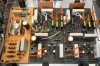
board_before.JPG
While I was at it, I also increased the value of the filter capacitor on the power board (marked in blue above) and the one attached to the big can capacitor from 100 µF to 220 µF.

Here is the 'after' shot:
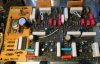
board_after.JPG

Unsurprisingly, this had no effect on the noise in the phono channel, and before you start, yes I know that the effect of swapping out the polyester film caps is likely to be marginal at best. I am also a sometime defender of ceramic caps but, in blind A/B tests, I will say that it is now easier to hear the difference between the C26 and the Pro-Ject Phono Box, especially at high-frequencies. For example, when listening to Astrud Gilberto's voice in, The Shadow of Your Smile, I cannot hear a difference between the two phono stages. In fact, when my wife is manning the Schiit, I cannot even tell when she flips the switch. When the strings take over, and shoot up into the higher registers however, I can definitely hear a difference, with the C26 usually sounding more 'airy'.

 
Last edited:
Here is a cautionary tale. I present it as a brief palette cleanser. Something you can read between all the success stories about the sonic benefits of replacing this or that capacitor or resistor.

I started work on the power supply of the C26, hoping, among other things, to stabilize the voltage rails and reduce some of the noise in the phono channel. To figure out how much difference the changes make, I recorded the noise from one phono channel with the volume set at max. I used a Blue Yeti microphone set for cardioid recording pattern and positioned 24" from the center of the speaker (and 47" from the floor). I chose the cardioid pattern and close recording position to reduce room effects.

mic_setup.jpg

Here is a power spectrum of the noise profile (calculated by Audacity) with the tone controls set to flat (yellow) or with two clicks of bass boost (blue). Obviously the validity of this approach depends on the quality of the microphone and the reproducibility of the measurements, so the clear differences at low frequencies and the close agreement at higher frequencies give me some confidence that I can detect differences in overall noise levels.

phono_flat_bass2_compare.jpg
 
Last edited:
Need to take measurements directly at the preamp outputs for testing the preamplifier. Readings taken at the loudspeaker are completely useless for this type of analysis.
 
Last edited:
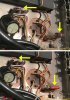
So, with baseline data in hand, I decided to look at the effect of replacing some of the carbon resistors in the power supply with metal film. I picked resistors with tighter tolerances and higher power ratings (2X) than the original. Here are two from the bottom side of the chassis.

power_resistor_change.jpg

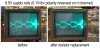
According to my meter, the old resistors were still in spec and changing them did not significantly affect the 9.5V supply rail voltage, which I measured at 8.88V before and after swapping the resistors. The 75V rail was 68.9 before and after the swap. So far, not much to report. The big surprise came when I looked at the ripple/noise on the supply voltages. Here are the oscilloscope probes attached to ground and +9.5V on both channels.
probe_positions.jpg

Disappointingly, after swapping the old carbon resistors for metal films the high frequency noise on the supply voltages actually increased! The ripple is also slightly increased.

scope_traces.jpg

The traces above show the signal from the 9.5V supply rail measured on the left and right channel boards. The DC component has been removed and the polarity of the right channel is reversed so that you can see both traces and get a sense of the peak-to-peak variation, which turns out to be about 0.25V, or 2.6%. Note how much 'hairier' the trace on the right has become.
 
Last edited:
Need to take measurements directly at the preamp outputs for testing the preamplifier. Readings taken at the loudspeaker are useless for this type analysis.

I beg to differ.

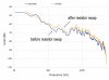
Here is where the baseline noise measurement comes in handy. To see whether the audible noise in the phono channel was affected by the increased noise in the pre-amp supply voltage, I re-measured the output from the speaker and compared it to the baseline.

before_after_compare.jpg

Note that this measurement is made with the gain turned ALL THE WAY UP. While my subjective impression under these conditions is that the noise is significantly louder (and the measurement bears that out), at normal listening levels I don't really notice a difference.
 
Last edited:
The white LES’s are too bright in the McIntosh gear. Well, I suppose you may be able to find a suitable brightness level, but......I haven’t ever. I went back to the old, stock lamps, and my McIntosh equipment now all matches. When I tried the white LED’s in My MC2105, it washed out the green lettering too much, and it did not match my preamp, C3, with the stock bulbs.
 
So I guess what you are implying is that the old carbon resistors were acting as a "filter" to restrict some of the hash on the DC supply.

I bypass the multicap with individual caps and have added film caps at the board's DC inputs and tried bypasses at the new multicap replacements.

A couple of tag lugs work well to make a neat replacement job.
 
So I guess what you are implying is that the old carbon resistors were acting as a "filter" to restrict some of the hash on the DC supply.

I bypass the multicap with individual caps and have added film caps at the board's DC inputs and tried bypasses at the new multicap replacements.

A couple of tag lugs work well to make a neat replacement job.

I was surprised by the result and I don't have a good explanation. Some sort of filtering makes sense, but I generally think of carbon composition resistors as having negligible inductance so I am not sure where the filtering would come from.

Anyway, I am leaving the new resistors in place and will move on to the capacitors in a few weeks. I like your suggestions and look forward to doing a bit of experimenting.
 
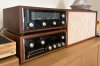
Thanks for the ping! I haven't had time to do any more work on the C26, but I did get it a new friend to play with: an MR73 tuner.

I know that a lot of people prefer the MR74, but these guys sound pretty great together.

IMG_2230.JPG
 
Back
Top Bottom