

You are using an out of date browser. It may not display this or other websites correctly.
You should upgrade or use an alternative browser.
You should upgrade or use an alternative browser.
My Sansui 3000a Restoration
- Thread starter jheu02
- Start date

Ended up ordering new 800 ohm 1% 7W resistors to finish off the TRZ-2D board and they showed up today. So, here's the finished board. In the meantime I cleaned the speaker and loudness switches and found that the CC resistors here through the volume, bass, and treble pots were mismatched...one fairly close to spec, but the other off more than I'd like for each channel, so they got replaced with Dale RN or CMF series while I was at it. I think that about all that's left to do is replace the 3000uF main filter caps and the one other 1000uF and then see how it works (or doesn't if I screwed something up  ). Oh, also need to breadboard the output coupling caps (3 for each channel paralleled) and run the new wires per the service bulletin.


). Oh, also need to breadboard the output coupling caps (3 for each channel paralleled) and run the new wires per the service bulletin.
Last edited:

Looks good. Keep an eye on the left 2 driver transistors when you fire it up. Since they are mounted backwards, they may not dissipate heat as well as the right pair. I don't think they get hot at all, so it shouldn't be a problem, but something to watch out for. Hard to tell from the photo, but did you stand the new resistors off of the board? not critical, but it helps keep them and the board cooler by increasing air circulation.
Rich
Rich
Yes, resistor legs are bent to form standoffs before entering the board. I did use thermal compound on the two reverse-mounted Qs, and since they are rated to 4A continuous, assuming they see a fraction of that (due to the success of others using the KSC2690 with its 1.2A rating and fully plastic case), I think I should be good, but definitely something to keep my eye on.
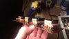
Decided to replace the DS1N rectifiers in the diode stacks. Only had 6 1N5408s (3A 1000V) and 6 1N5404s (3A 400V), so decided to use the 5404s (3 each board with the remaining one in each board being a 5408). 400V should be plenty high for this use. I had some ultrafast rectifiers, but figured that would be a waste in this amp. Though D007-010 all checked fine, 2 in the D003-006 board were toast. IIRC, that Left channel also had one of the SM-150s bad on the pre power board (TRZ-2D). So, glad I didn't just leave them alone, as thast may have been the cause for the initial pulsing dim bulb.
Some of the other work that's been done.
Switches with new resistors as mentioned previously

Diode Stacks

Main Filter Caps and the 1000uF other ripple filter. Sure look shrimpy compared to the originals. PVC spacers for the replacement UHE series 1000uF/63V.

Trace side of Main Filters

Coupling Caps for the Service Bulletin (the spaces in each PVC ring have now been filled with silicone caulk).

Switches with new resistors as mentioned previously
Diode Stacks
Main Filter Caps and the 1000uF other ripple filter. Sure look shrimpy compared to the originals. PVC spacers for the replacement UHE series 1000uF/63V.
Trace side of Main Filters
Coupling Caps for the Service Bulletin (the spaces in each PVC ring have now been filled with silicone caulk).

I've never seen anyone install the coupling caps that way. Clever.Coupling caps mounted

I need to rehab my 3000A again sometime. When I first rebuilt it, I only had a 3000 service manual, so I backdated some of the circuitry that had failed to the earlier configuration. I need to go through it again now that I have a proper 3000A service manual, and probably improve some of my earlier work - including some of the circuit traces which are still intact but popped up from the boards when I was trying to desolder the infamous Sansui folded-over leads. Part of me just wants to make a new set of boards and order them from one of the inexpensive board suppliers.
Great solution for mounting the coupling cap 'bundles'. I'll have to keep that in mind going forward. I recently picked up a 3D printer so I should be able to fabricate custom versions of something like that. Soooooo . . . how's it sound?
Rich P
Rich P

Great solution for mounting the coupling cap 'bundles'. I'll have to keep that in mind going forward. I recently picked up a 3D printer so I should be able to fabricate custom versions of something like that. Soooooo . . . how's it sound?
Rich P
Haven't quite finished all the hookups for the pre-power board. Had dinner guests and other things going on. Brewing today, but will hopefully have the time to finish it off and check it out. Regarding the clamps, they were left-over from an SX-780 IIRC (made my own out of sheet metal. They are a tad large, so had to bend the extra supports under the clamp, and unscrew the fuse board to be able to get the mounting screw for the clamp in sideways AFTER I got the shield screw into the chassis. Smaller custom clamp would be better and not require the PVC spacer.
EDIT: I also just decided to replace the two rectifiers on the ripple filter board, going from 1N4007 to MUR260s. In extra searches I found that the SW-0.5a original rectifiers may have been 1.5A rated, so the 4007s would have been a little underrated at 1A. The MUR260s are 2A 600V ultrafast recovery. And will have to do the same with D011, the rectifier on the light string (unless I were to replace all of the lamps (except 28V protect) with LED.
Last edited:
Have fun brewing. I started back in 1991 . . . great hobby.
MUR260s are a good option to replace 1.5A diodes. I keep a pile of FR207s (2A, 1000V) on hand for applications like that. 1N54xx are overkill and don't fit well. I'm always surprised to see recommendations to use them in place of smaller parts.
Rich
MUR260s are a good option to replace 1.5A diodes. I keep a pile of FR207s (2A, 1000V) on hand for applications like that. 1N54xx are overkill and don't fit well. I'm always surprised to see recommendations to use them in place of smaller parts.
Rich
Have fun brewing. I started back in 1991 . . . great hobby.
Rich
1989 for me...
Everything's hooked up and it passed the DBT. Now to go back over the posts about setting bias and cancelling any DC Offset. I have several DMMs, but only one set of mini grabbers. I suppose if I use the SM procedure, I could use alligator clips on the fuse holders, yes??? I'm much more used to setting mV across emitter resistors though. Thoughts?
In another post, someone posited that the equivalent mV reading across the emitter resistors would be 24mV with unchanged 0.3ohm resistors (80mA x 0.3 ohm = 24 mV). Now that I've changed the Rs to the 1 ohm recommended in the SB, should I really set 80mV? Seems awfully high, but it is Ohm's Law after all....
I've never seen anyone install the coupling caps that way. Clever.
I was originally intending to breadboard the caps and use standoffs. But I wasn't confident of the long term stability (physical) for these relatively large caps mounted horizontally, with just solder connections holding them. And since I had the clamps from another restore, it seemed like a logical use for them.
Oh, one last question before I adjust the bias...
Several threads state not to have a dummy load hooked up until AFTER bias is set...dummy load only for tweaking the DC Offset.
Other posts, as well as the SB, state to use the dummy load before setting bias.
Leaning toward just following the SB and hooking up a dummy load and also using the emitter resistor method as I find it more stable to have the amp sitting on the whole frame vs on one side. Suppose I could always pull the two fuses from the channel NOT being biased at the time so no funny business happens. From all the cautions in various threads, this amp has me a bit spooked to set this vs all the others I've done.
Several threads state not to have a dummy load hooked up until AFTER bias is set...dummy load only for tweaking the DC Offset.
Other posts, as well as the SB, state to use the dummy load before setting bias.
Leaning toward just following the SB and hooking up a dummy load and also using the emitter resistor method as I find it more stable to have the amp sitting on the whole frame vs on one side. Suppose I could always pull the two fuses from the channel NOT being biased at the time so no funny business happens. From all the cautions in various threads, this amp has me a bit spooked to set this vs all the others I've done.
Got it all biased up...I left it a little low (76mA) vs 80 in case of creep. Then did a short listening test. A little hum in the background...was worst on the Tape HD (not the Tape Monitor) but went down to the background level once I put grounding plugs in the inputs. So, I'll need to go through and check all the grounds and the input caps to ground (C023-026 0.05uF). Volume pot also doesn't get completely quiet, so will give it a good F5 lube and see if that will help a bit. Anyone ever add any resistors in series where the wires connect to fix this vs trying to find a new pot with loudness tap?
Other observations and questions....
FM Stereo Indicator: How is this supposed to look when operating correctly? I've read somewhere about orange and green lighting and stereo indicator flickering, but mine doesn't do anything like that. The front bulb on the Left side of the front panel (PL501) that hooks up to the FM Stereo Indicator board (TRI-1A) was burned out and has been replaced by an LED/resistor combo in the screw base. It is ALWAYS lit. The green tinted one that sits behind it (PL003) is still good and only lights when Tuner is selected. The two trimmers on the indicator board are still original, and had marker marks on them, so I turned them a bit in either direction, but no change. Same when I select MONO, the bulb is still lit, though I can definitely hear it go from stereo to mono.
Other observations and questions....
FM Stereo Indicator: How is this supposed to look when operating correctly? I've read somewhere about orange and green lighting and stereo indicator flickering, but mine doesn't do anything like that. The front bulb on the Left side of the front panel (PL501) that hooks up to the FM Stereo Indicator board (TRI-1A) was burned out and has been replaced by an LED/resistor combo in the screw base. It is ALWAYS lit. The green tinted one that sits behind it (PL003) is still good and only lights when Tuner is selected. The two trimmers on the indicator board are still original, and had marker marks on them, so I turned them a bit in either direction, but no change. Same when I select MONO, the bulb is still lit, though I can definitely hear it go from stereo to mono.
Got it all biased up...I left it a little low (76mA) vs 80 in case of creep. Then did a short listening test. A little hum in the background...was worst on the Tape HD (not the Tape Monitor) but went down to the background level once I put grounding plugs in the inputs. So, I'll need to go through and check all the grounds and the input caps to ground (C023-026 0.05uF). Volume pot also doesn't get completely quiet, so will give it a good F5 lube and see if that will help a bit. Anyone ever add any resistors in series where the wires connect to fix this vs trying to find a new pot with loudness tap?
Other observations and questions....
FM Stereo Indicator: How is this supposed to look when operating correctly? I've read somewhere about orange and green lighting and stereo indicator flickering, but mine doesn't do anything like that. The front bulb on the Left side of the front panel (PL501) that hooks up to the FM Stereo Indicator board (TRI-1A) was burned out and has been replaced by an LED/resistor combo in the screw base. It is ALWAYS lit. The green tinted one that sits behind it (PL003) is still good and only lights when Tuner is selected. The two trimmers on the indicator board are still original, and had marker marks on them, so I turned them a bit in either direction, but no change. Same when I select MONO, the bulb is still lit, though I can definitely hear it go from stereo to mono.
Mine is still running on the original bulbs. Some of the behavior is a bit flaky, as it was mostly the FM/MPX circuitry that I had to backdate to the 3000 spec from the 3000A design due to the lack of a 3000A manual when I was working on it (specifically, one whole channel of the MPX board was blown out, among other issues), but the FM Stereo light definitely doesn't stay lit.