• The move to the new server is done. There are some software and database maintenance updates in process. This has us passing the hat around to help out. We appreciate any donations. Seriously, even a dollar helps. The payment page may be found here - https://www.audiokarma.org/support.html

My Sansui 3000a Restoration

@Sam Cogley

Any ideas where to look? I did test all the Qs on the board, but I'm wondering if either the 2SB324 or B54 could be leaky. I guess I should also pull the trimmers and check ooc. There’s not much info in the troubleshooting section other than those two Qs and the trimmers being bad. Voltage checks to come.
 
So, to answer my own question…after downloading the owners manual, it appears that the Signal Strength meter doubles as the Stereo indicator, which is why both bulbs are near it. The meter glows greenish blue (rearmost bulb) any time a mono signal is present. Once a stereo signal is present, the front orange bulb (PL501) is supposed to turn on. I guess proximity to the meter is what allows it to “override” or “overpower” the greenish lamp, as I don't believe the green lamp extinguishes simultaneously.

now to figure out why the stereo lamp stays lit all the time. Haven't looked to see if the Mode switch set to mono will cut it off, and as I'm out of town for work, it will have to wait.
 
Mine was stable holding stereo. Tuned stereo like you would normally expect. DId have to do a rough alignment of the front end using some weaker stations on the dial to get it tuning a lot better. Been a few years need to open mine up remember exactly what I did. Remember the tuning meter would stay greenish when not on station but when receiving stereo ended up reddish orange when the stereo bulb came on. I think I had to tweak the bulb positions to get it to look better and the stereo bulb dominate over the green when it came on by bending their brackets a little. I remember getting bulbs from dgwojo got some different colored stretchy sleeves to slip on, basically colored translucent condoms for those bulbs to make a white LED bulb look different colors. Used green LED fuse lamps at the end of the tuning dial. One problem with cell phones especially lower end ones the cameras can't handle the same contrast the human eye can.

Have to watch those switches. Was in a Sansui 800 of the same vintage they were lever switches but same internals behind them as the 3000A rockers and all the brass inside was dark. Sometimes you need to take them apart hard to see how deoxit could do a lot. I showed what I did with one in the 800 starting post #19 on this thread can see how bad it still was even after using Deoxit. Had to take apart the speaker selector rocker on my 3000A to get System A working on both channels again. One strip was curved the other was straight. Figure it had fried a woofer in the past. The oxidation level on the 3000A speaker selector switch internals was far less than the 800 one.
https://audiokarma.org/forums/index.php?threads/sansui-350a-restoration-questions-dc-offset.1027156/

Need to dive back in mine sometime, amplifier section still has some stability issues would drift around on DC offset sometimes would kick the protection lamp on. Sits on a shelf with some other to revisit for more repair.

At minimum volume mine is not silent either, sort of sits at a lower volume good for a softer level of music playing in the background. At least both channels sound the same level. I have seen a number of others post that their units are not silent at minimum volume. Seems to be an affliction of the 3000A.
index.php
 
Thanks. I definitely get a good stereo signal, and can hear the change to mono when switches, but the front stereo bulb stays illuminated. Currently in Berlin, but will look again this weekend.

I disassembled all the rocker switches and cleaned them with a pink eraser, with D5 follow up, so no issues with any of them.

And the stereo light isn't a big deal, aid just like to get it working correctly in case I pass it on to someone someday. I do want to track down the hum though...all new caps on the ripple and main filters, so it could just be all the wiring running close together, or maybe the caps to ground on the phono and tape head inputs.
 
The stereo lamp grounds through TR505 to turn it on. Make sure it isn't shorted and check C504 which bridges E-C on TR505 to make sure that isn't shorted as well. If those simple things are OK, you'll have to figure out what's going on with the circuit feeding the base of TR505. Measure voltage there and see what happens when you tune into and out of a stereo signal. It gets complicated from there if you haven't worked with tuners before . . .

Rich
 
The hum in phono....

In searching it as a general topic, I came across posts about some Marantz units which, with the bottom and top covers off, had the same issue, but once replaced the hum went away. Well, this is another one of those units... Put the bottom cover and some other parts on and the hum is gone! There's the noise floor, which I wish was a little quieter, but it's just a shhhhh, not humMM, and the volume knob has to be up quite a bit for it to be heard with no source material playing.

Now to play around with the stereo signal for FM a bit more. I did remove the board and desolder the trimmers to check if they were to blame, but they test good, and the Qs that I hadn't replaced (including TR505) I retested, to no avail. C504 I replaced with UKL series) So, will have to hook up the antenna and go through the SM procedure to adjust them again and see if anything changes. The troubleshooting guide does say that a weak transistor could cause flickering stereo light, so....
 
Last edited:
WELL....The hum has nothing to do with the receiver! It has to do with the turntable that's hooked up to it. Currently running our main TT on it and there's no hum at all. Now to figure out the TT hum.
 
Now to try and tackle the volume pot issue. Like others, if I have the tuner selected, even at minimum volume, you can listen to it. So, my thought on trying to tackle this without buying a replacement pot that may or may not fit/work correctly is to add a series resistor to each channel that feeds the volume pot. I have tons of Dale RN60Cs which I could use, and I could potentially insert a trimmer into each circuit to dial it in for silence at min volume and then select the nearest single value R. Is there a reason to NOT try this? Or, should I just adjust the value of R702/728 at the input of the TRM-3a board AFTER the volume pot?
 
Help requested:

OK, so I'm trying to track down the stereo light issue by measuring voltages on the various boards. IF I'm measuring in the correct places, I could be getting some wonky readings that could indicate issues with the MPX board, etc. And if this is correct, why I'm getting a stereo signal (or FM for that matter) at all is curious. So, take a look at the below scat. I've highlighted the voltages at the various transistors in yellow, and other voltages with what I think are the associated points to measure them. I'm specifically interested in these other points, especially the red and magenta ones that I THINK are associated with the OA79 diodes. Clicking the scat will take you to the full size for easier reading.

Does it look like I'm taking my readings in the correct locations?
3000aMPX_Volts.jpg
 
Last edited:
Been working other projects , but want to finish this one up soon. I may give up on the stereo light issue, but here's what I plan to try for the volume pot issue. R702, 728 on the TRM-3a board are the first connections AFTER the volume pot. So, I plan on trying higher value MF resistors to see if I can block the bleed through at min volume. Perhaps start at 50K and going as high as 125K since mine may have measured that, yet is supposed to measure 250K. If it doesn’t work, I can always try the replacement pot listed in a different rebuild thread.

anyone see any problems with this plan other than it will always present that resistance vs being variable like a pot would be? Perhaps start even lower than 50k, or use a trimmer to find the best compromise value before fixing the value?


IMG_0685.jpegIMG_0686.jpeg
 
Been working other projects , but want to finish this one up soon. I may give up on the stereo light issue, but here's what I plan to try for the volume pot issue. R702, 728 on the TRM-3a board are the first connections AFTER the volume pot. So, I plan on trying higher value MF resistors to see if I can block the bleed through at min volume. Perhaps start at 50K and going as high as 125K since mine may have measured that, yet is supposed to measure 250K. If it doesn’t work, I can always try the replacement pot listed in a different rebuild thread.

anyone see any problems with this plan other than it will always present that resistance vs being variable like a pot would be? Perhaps start even lower than 50k, or use a trimmer to find the best compromise value before fixing the value?


View attachment 3048312View attachment 3048313
This link is to a reply from @Richard P to my mention of the volume pot issue on this unit from some time back. Perhaps may be of use?
 
anyone see any problems with this plan other than it will always present that resistance vs being variable like a pot would be? Perhaps start even lower than 50k, or use a trimmer to find the best compromise value before fixing the value?

I believe I tried adding resistors to the inputs of the volume pots and it did nothing if i recall correctly. I'll be curious to see what result you get. Since you've already rebuilt the TRM-3A board, replacing the pot may be the only solution.

Rich
 
It shouldn't be too hard to access the board, but I'm away for work. Hopefully I have a trimmer that's of decent value and see what I may be able to get away with. Seems like it will shift how far I need to turn the volume knob to get an appreciable increase in volume, which may actually be a good thing. As it stands now, I don't turn the knob very far before it gets plenty loud
 
Seems like it will shift how far I need to turn the volume knob to get an appreciable increase in volume, which may actually be a good thing. As it stands now, I don't turn the knob very far before it gets plenty loud
True, I rarely turn mine past 10:00 before it's too loud for normal listening.
 
Got home last night from my work trip. Found a 100K trimmer and set it to 2K in R728 (it got very finicky at that low end so couldn't get it to 1K). Kept trimming but still had sound out of the Right channel. Took it out and measured it at 98K, so I had trimmed it fully for my purposes. Tried a couple other higher values, ending with 249K and still had sound at min volume, and it didn't seem to change the increasing volume as I turned the knob...still plenty loud with a small turn. This doesn't make sense to me, so, I'm wondering if there's some wire reversal coming off the pot...either I hooked up the wires incorrectly when rebuilding the receiver, or if there's some other explanation. I took lots of photos to assist the reassembly, but who knows. In any case, looks like I need to order a new volume pot.
 
New volume pot arrived and is installed. Now there's a hum I don't recall having before, so perhaps one of the ground wires didn't get soldered properly, or I missed one in the process. It DID however, cure the volume bleed through at the minimum setting. I wonder if Sansui just got a mismarked batch of pots, as mine also measures in the 130K range. Haven't opened it yet to see if the wipers are just misaligned.

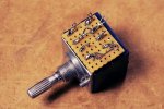
Having done some other reading, not sure if this is a genuine ALPS pot, but it measures well and does the job. Since the loudness taps are on the far side of the pot vs the way the original pot was designed, (the two on the top in the photo) I had to run new wires from the loudness switch, the originals were too short to reach. The threaded part for the nut is slightly larger than the original opening in the chassis, so I had to enlarge the hole a little, but the pin lined up nicely. I also had to use my Dremel and wire brush to clean the knurled portion for the knob to slide on correctly. Though they appeared to be identical in size, the knob just wouldn't fit properly. In case anyone else uses this type of pot to repair theirs in the future, here's the pinout:

1 - Ground
2 - Output
3 - Input
4 - Loudness

Here was my solution to the issue with lots of wires having to go to a pin-style pot.

ePXKP2798.JPGePXKP2799.JPG
 
I also had to use my Dremel and wire brush to clean the knurled portion for the knob to slide on correctly. Though they appeared to be identical in size, the knob just wouldn't fit properly.
Great job. Interesting that the knob didn't fit on yor Alps pot. I had the same issue but figured is was because i ordered my pot from China. I guess the Sansui knob splines run on the small side. Good luck with the hum issue.
 
Further question...what do you all use to replace the stranded wire that has the ground (shield) running along it like pictured here. This UL1533 or UL1185 is only rated to 80 C, but not sure if that's important. Any US suppliers?
 
I have a box of shielded cables i've pulled from parts units over the years so I can't comment on current suppliers, but the ones you linked would be fine I would think. Just watch out for single ended ground connections vs connections at both ends. It can make a difference in some places. Just replicate what you pulled out.
 
Last edited:
I did just touch up the solder on the Left (front) ground connections, and for good measure ran a ground wire down to the chassis. That cleaned almost all of the hum up. I seem to recall that when I first rebuilt it, there was a slight hum, which cleared further once I put the bottom cover back on. So, will try that later, but have a loaf of sourdough in the oven and don't want to get too distracted.
 
Back
Top Bottom