

You are using an out of date browser. It may not display this or other websites correctly.
You should upgrade or use an alternative browser.
You should upgrade or use an alternative browser.
Register to hide this ad

Ylli
Super Member
Well, let's start somewhere in the middle. I assume you have a multi-meter, how about a scope or other test gear? Don't need it for the following, but for future reference..
With the unit set to FM, in Stereo mode: Find Q209, it's a 22 pin IC near the inputs. Using a sharp metallic object, such as a needle or pin, make contact with Q209 pin 4. You should hear a hum out of one of the channels. Now do the same for Q209 pin 19. Should hear a hum on the other channel. Now try pins 3 and 20. The induced hum should be very close to the same level as you had on pins 4 & 19.
With the unit set to FM, in Stereo mode: Find Q209, it's a 22 pin IC near the inputs. Using a sharp metallic object, such as a needle or pin, make contact with Q209 pin 4. You should hear a hum out of one of the channels. Now do the same for Q209 pin 19. Should hear a hum on the other channel. Now try pins 3 and 20. The induced hum should be very close to the same level as you had on pins 4 & 19.
Hi -Yes have MM, no scope. I have limited knowledge, but know basics. Never messed with ICs though but see q209 and numbering of pins. I assumed lower board is preamp and top board is tuner? All inputs on preamp work fine, just tuner has issue. I assume I can touch pin with mm probe?Well, let's start somewhere in the middle. I assume you have a multi-meter, how about a scope or other test gear? Don't need it for the following, but for future reference..
With the unit set to FM, in Stereo mode: Find Q209, it's a 22 pin IC near the inputs. Using a sharp metallic object, such as a needle or pin, make contact with Q209 pin 4. You should hear a hum out of one of the channels. Now do the same for Q209 pin 19. Should hear a hum on the other channel. Now try pins 3 and 20. The induced hum should be very close to the same level as you had on pins 4 & 19.
Ylli
Super Member
Yes, you can touch the pins with the meter probe. We are trying to inject some 'hum' into the audio path and see if we can determine where it is not getting through. So we actually want you to make electrical contact with the IC pin with your body. So (for example) hold on to the metal part of that needle and touch the IC pin. You do want to be careful not to short to adjacent pins.
touching an electrical component while plugged in? I may be a novice but that sounds like a bad idea. Seems like you could take a voltage reading somewhere to determine that.Yes, you can touch the pins with the meter probe. We are trying to inject some 'hum' into the audio path and see if we can determine where it is not getting through. So we actually want you to make electrical contact with the IC pin with your body. So (for example) hold on to the metal part of that needle and touch the IC pin. You do want to be careful not to short to adjacent pins.

Can't inject a noise by measuring a voltage.Seems like you could take a voltage reading somewhere to determine that.
IC pins have around 5 - 18 volts DC potential. Nothing lethal.I may be a novice but that sounds like a bad idea.
Ok, thank you for that, just being cautious! Will take a look at tomorrow.Can't inject a noise by measuring a voltage.
IC pins have around 5 - 18 volts DC potential. Nothing lethal.
Ylli
Super Member
When hooking up a CD player, phono, or other external device, have you ever touched the center pin of the RCA connector you are connecting to the external device? If so, you likely heard a loud hum. Your body picks up the AC field in the environment and conducts it to that input cable.
You are doing the same when you touch a pin in the signal chain. You are 'injecting' the low amplitude/low current AC voltage that your body is picking up from the environment into the signal path. It is really like a poor man's signal generator.
As for your personal safety, you need to stay away from the line voltage and in most amplifiers you need to stay clear of the +/- rails that feed the power amp. I would not ask you to touch anything that would have any dangerous voltages on them. That said, you are right to be cautious. A trick for added safety is to use only one hand and keep the other 'behind your back' i.e. away from the circuitry/chassis. That way if you do come in contact with a dangerous voltage, the current path will not be across your chest and through your heart where it can do the most damage.
The points I indicated are the input and outputs of the solid state switch that selects the desired input. DC voltage levels here are near zero, and even if you would touch the power pins on this IC you would be seeing only +/- 18.5 volts. That voltage is not enough to create a 'shock' when applied externally to a normal human body.
The 'plan' is to use this poor man's signal generator and follow the signal path forwards or backwards until we find the place where the signal is being blocked.
You are doing the same when you touch a pin in the signal chain. You are 'injecting' the low amplitude/low current AC voltage that your body is picking up from the environment into the signal path. It is really like a poor man's signal generator.
As for your personal safety, you need to stay away from the line voltage and in most amplifiers you need to stay clear of the +/- rails that feed the power amp. I would not ask you to touch anything that would have any dangerous voltages on them. That said, you are right to be cautious. A trick for added safety is to use only one hand and keep the other 'behind your back' i.e. away from the circuitry/chassis. That way if you do come in contact with a dangerous voltage, the current path will not be across your chest and through your heart where it can do the most damage.
The points I indicated are the input and outputs of the solid state switch that selects the desired input. DC voltage levels here are near zero, and even if you would touch the power pins on this IC you would be seeing only +/- 18.5 volts. That voltage is not enough to create a 'shock' when applied externally to a normal human body.
The 'plan' is to use this poor man's signal generator and follow the signal path forwards or backwards until we find the place where the signal is being blocked.
Last edited:
Thank you for this and appreciate the detailed explanation. I will try tonight and report back.When hooking up a CD player, phono, or other external device, have you ever touched the center pin of the RCA connector you are connecting to the external device? If so, you likely heard a loud hum. Your body picks up the AC field in the environment and conducts it to that input cable.
You are doing the same when you touch a pin in the signal chain. You are 'injecting' the low amplitude/low current AC voltage that your body is picking up from the environment into the signal path. It is really like a poor man's signal generator.
As for your personal safety, you need to stay away from the line voltage and in most amplifiers you need to stay clear of the +/- rails that feed the power amp. I would not ask you to touch anything that would have any dangerous voltages on them. That said, you are right to be cautious. A trick for added safety is to use only one hand and keep the other 'behind your back' i.e. away from the circuitry/chassis. That way if you do come in contact with a dangerous voltage, the current path will not be across your chest and through your heart where it can do the most damage.
The points I indicated are the input and outputs of the solid state switch that selects the desired input. DC voltage levels here are near zero, and even if you would touch the power pins on this IC you would be seeing only +/- 18.5 volts. That voltage is not enough to create a 'shock' when applied externally to a normal human body.
The 'plan' is to use this poor man's signal generator and follow the signal path forwards or backwards until we find the place where the signal is being blocked.
Ok touched the pins on the q209 IC, I didn’t hear any hum or change. Had tuner on fm stereo with amp on, nothing.Hi -Yes have MM, no scope. I have limited knowledge, but know basics. Never messed with ICs though but see q209 and numbering of pins. I assumed lower board is preamp and top board is tuner? All inputs on preamp work fine, just tuner has issue. I assume I can touch pin with mm probe?
Tuner plays right channel in fm no left. All other inputs good
Ylli
Super Member
I think the FM on the good channel is overwhelming the injected hum, so you do not hear it. Try this... Select FM. Turn the balance control to the left so that the right channel output is reduced/eliminated and you are listening only to the 'bad' channel. Now turn the volume up a bit and try touching those pins again. You may just hear a click and a bit of static or you may hear a definitive hum.
I hear now but only on pin 19 and 20I think the FM on the good channel is overwhelming the injected hum, so you do not hear it. Try this... Select FM. Turn the balance control to the left so that the right channel output is reduced/eliminated and you are listening only to the 'bad' channel. Now turn the volume up a bit and try touching those pins again. You may just hear a click and a bit of static or you may hear a definitive hum.
Ylli
Super Member
So pins 19 & 20 must be on the left, and the signal injected there is getting to the speaker. (You heard nothing on pins 3 & 4 because that would be the right channel and you have the right suppressed with the balance pot). We will need to back up to the tuner board.
Dog is in need, I'll post more a bit latter.
Dog is in need, I'll post more a bit latter.
Ylli
Super Member
Let's chase that signal back up into the tuner. With the receiver set as it was, FM stereo mode, balance fully left, and the volume cranked a bit:
Inject hum into the yellow highlighted point - P105. Got hum? good.
Now inject hum into the point circled in red - left end of R129/emitter of Q119. Got hum? good.
Inject hum into the point circled in blue - bottom of R127/base of Q119. Got hum? good.
Finally, lets inject at the point circled in green. Bottom of R125/input to the LPF. got hum? good.
The amount of hum you hear may actually get less as you move through the above, as there are losses in the circuitry. You can turn the volume up a bit if needed.

Inject hum into the yellow highlighted point - P105. Got hum? good.
Now inject hum into the point circled in red - left end of R129/emitter of Q119. Got hum? good.
Inject hum into the point circled in blue - bottom of R127/base of Q119. Got hum? good.
Finally, lets inject at the point circled in green. Bottom of R125/input to the LPF. got hum? good.
The amount of hum you hear may actually get less as you move through the above, as there are losses in the circuitry. You can turn the volume up a bit if needed.
Hi - I got hum (more of a crackle) everywhere except r125Let's chase that signal back up into the tuner. With the receiver set as it was, FM stereo mode, balance fully left, and the volume cranked a bit:
Inject hum into the yellow highlighted point - P105. Got hum? good.
Now inject hum into the point circled in red - left end of R129/emitter of Q119. Got hum? good.
Inject hum into the point circled in blue - bottom of R127/base of Q119. Got hum? good.
Finally, lets inject at the point circled in green. Bottom of R125/input to the LPF. got hum? good.
The amount of hum you hear may actually get less as you move through the above, as there are losses in the circuitry. You can turn the volume up a bit if needed.
View attachment 1602447
Ylli
Super Member
OK, now the question is how much loss is there normally in that low pass filter. Is the signal not getting through the LPF or is it just too weak to hear... Let's try it this way....
Add a short jumper wire from the bottom end of R191 to the bottom end of R192. We are jumping the audio signal from the operative right channel into the left. Center up the balance control and tune the radio to an FM station. Do you hear audio from both channels? (as an alternate to adding a jumper, you could probably just short the specified points with a flat blade screw driver, being careful not to short to anything else.)
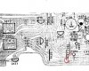
Add a short jumper wire from the bottom end of R191 to the bottom end of R192. We are jumping the audio signal from the operative right channel into the left. Center up the balance control and tune the radio to an FM station. Do you hear audio from both channels? (as an alternate to adding a jumper, you could probably just short the specified points with a flat blade screw driver, being careful not to short to anything else.)
Ylli
Super Member
RCA cable? Aren't we chasing a bad left channel on FM? What RCA cable are you referring to?
Assume your first attempt was right, and there is still no audio out of the left channel with the jumper as specified in #16, Move the jumper to connect points P105 and P106. Do you get sound out of the left channel?
We are trying to localize where the signal is being lost, and because some of these tests are subjective, we often have to work back and forth.
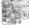
Assume your first attempt was right, and there is still no audio out of the left channel with the jumper as specified in #16, Move the jumper to connect points P105 and P106. Do you get sound out of the left channel?
We are trying to localize where the signal is being lost, and because some of these tests are subjective, we often have to work back and forth.
Just the rca cables of preamp out to amp...just wanted to double check those, but yes bad left channel. I know cables are fines just had been pulling them in and out and want to double check that. I’ll try the p105 106 tonight...fyi I am on east coast time. Thank you for your time and diagnosis! Btw I do get sound if mono is selected on both channels.RCA cable? Aren't we chasing a bad left channel on FM? What RCA cable are you referring to?
Assume your first attempt was right, and there is still no audio out of the left channel with the jumper as specified in #16, Move the jumper to connect points P105 and P106. Do you get sound out of the left channel?
We are trying to localize where the signal is being lost, and because some of these tests are subjective, we often have to work back and forth.
View attachment 1602707