
Ylli
Super Member
Good info, even though I haven't figured out how this processor controlled unit actually switches to monoI do get sound if mono is selected on both channels.



Good info, even though I haven't figured out how this processor controlled unit actually switches to monoI do get sound if mono is selected on both channels.
Ok I do get sound out of other channel when I jumper p105, p106...but not on r191, r192Just the rca cables of preamp out to amp...just wanted to double check those, but yes bad left channel. I know cables are fines just had been pulling them in and out and want to double check that. I’ll try the p105 106 tonight...fyi I am on east coast time. Thank you for your time and diagnosis! Btw I do get sound if mono is selected on both channels.
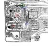
One thing I noted is heatsink q551 is fairly warm even when the unit is powered off. Plugged in but powered off.Ok I do get sound out of other channel when I jumper p105, p106...but not on r191, r192
R137=.03One thing I noted is heatsink q551 is fairly warm even when the unit is powered off. Plugged in but powered off.
R137=.03
R128=.03
R130=.68
R132=0
oops missed that one...had to head out will check late tonight, sorryR129?

You were right on r129. .68 ....jumpered 127,128 and got sound on leftBased on the base voltages, I suspect R129 will be right around 0.68 volts. If so, the numbers are good, and the two transistors are probably OK. If the voltage on R129 is not around 0.68 volts. Stop and let me know.
So we jumpered the inputs to the filters (R191/R192) and the left signal did not get through. Let's try jumpering on the outputs of the filters. Jumper bottom of R127 to top of R128.
View attachment 1603382
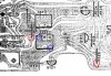
Some of the solder did look suspect but no luck, solder wasn’t drawing in to joint well though...I couldn’t find flux, so maybe that was issue. Anyway did best I could w/ no luck, did get sound jumpering 125 127.Review..
Jumpered filter inputs together, no sound on left.
Jumpered filter outputs together, sound both channels.
[Just noticed the layout and schematic have a minor inconsistency. The designators for Z111 and Z112 are reversed. On the schematic, Z112 is shown as the left filter, but on the board layout Z111 is shown as the left filter.]
Has to be a bad filter, or crack in the solder/foil between our R191 test point and the filter, or from the filter to our R127 test point.
Get out a magnifying glass and a good light source and look very closely for any cracks. Then I'd like you to reflow the solder connections on the Low Pass Filter Z112 (Layout designator Z111).
If the above does not fix it, then we will need to confirm a bad filter. Try a jumper between low end of R125 and low end of R127 - red circles. You *should* have audio on the left channel. If you do, then disconnect the R125/R127 jumper and add a jumper directly between the input and output of filter Z112 (Z111 on the layout) - blue circles. Audio on left?
View attachment 1603691
What kind of solder are you using? Should be electronics grade rosin core - extra flux should not be needed.solder wasn’t drawing in to joint well though

Got it I see no runs on those...no short on that red circle, reflowed others. No luckGood on the solder. The pins that are on pads with no runs do not need to be soldered. One input pin, one output pin, one ground, then the two mounting lugs. Looking at the picture... Confirm there is not a short in the red circled area. Then, did you reflow the solder on the blue circled pins? Hard to tell from a picture, but it looks like there may be some cracking on the blue circle pins.
View attachment 1604242
Yes it plays when I jumper them. That sucks that the part may be impossible to get, but hey I had a fun going though this and learned a few things...been a while since I did this stuff. I really appreciate the help again, pretty amazed at your knowledge here. I will try to find part!And if you add a jumper between the input and the output as posted in #31 you have audio on both channels? Then the filter itself is bad. Going to be a challenge to find a replacement part.
How does it sound with the part bypassed? It's a low pass filter to remove any residual 19KHz stereo pilot tone from the audio. Unless you have exceptional hearing or play the thing at extreme high volumes, shouldn't cause any problems. I'll search a bit more for a part too.[/QUOTE
Cool, so I could jumper it and just leave it I gather..I didn’t listen long so would have to give a try. Could you jumper with a capacitor across to act as the filter? Not that I could hear that frequency but curious
