• The move to the new server is done. There are some software and database maintenance updates in process. This has us passing the hat around to help out. We appreciate any donations. Seriously, even a dollar helps. The payment page may be found here - https://www.audiokarma.org/support.html

NAD 2200PE upgrading

streetwise

Active Member
I have a 2200PE that I would like to upgrade a few old caps. I have to redo the relays anyways, My curiosity is that I read about
All "PE" Series products:
This line was designed with a variable power supply, with the idea of conserving energy. (The British have an bug about this, left over from WWII rationing) At your option we can eliminate this feature and increase sound quality and bass extension. This can be done at no additional charge with a repair, please inquire.
---? how do I do this?
I also read about changing the values of caps 215-218 to 470uF/35V to "restore the bass". Any other ideas about changing values for perfomance?
 
Register to hide this ad
NAD's dual rail barely qualifies as variable power supply. Carver's Magnetic Field Amplifier is a voltage on demand design which allows for a smaller transformer to be used. I digress. My guess is you want to eliminate the upper voltage rail and the switch over distortion that comes with it? If so, you will end up with a low voltage rail amp that is not particularly fast. In stock form and at low volumes (when operating on the low voltage rail only), the 2200PE sounds compressed and somewhat dull. IMO, disabling the higher voltage rail and somehow increasing the output of the lower rail to compensate for the loss of power is not a great proposition.

I don't know about specific 2200PE tweaks but I would replace the PCB trimmers as they are of poor quality.
 
There are several upgrades you can make to bring the amp up to spec. Tried to upload as a file but didn't work so here they are in full:

Left,Right Channel
------------------
C101,102 0.82uF polycarbonate
C103,104 0.82uF polycarbonate
C105,106 2.2nF polystyrene
C107,108 1nF polystyrene
C109,110 replace with short if servo, else shunt with 2uF polypropylene
C111,112 10uF tantalum
C113,114 10uF tantalum
C115,116 replace with short if fitted

C201,202 180pF polystyrene
C203,204 replace with short if servo, else shunt with 2uF polypropylene
C205,206 470pF polystyrene
C207,208 replace with short if servo, else shunt with 2uF polypropylene
C209,210 0.1uF polypropylene
C211,212 390pF polystyrene
C213,214 100uF tantalum
C213a,214a 2uF polypropylene
C215,216 1000uF electrolytic
C215a,216a 2uF polypropylene
C217,218 1000uF electrolytic
C217a,218a 2uF polypropylene
C219,220 47uF tantalum
C221,222 47uF tantalum
C223,224 1uF stacked mylar

C301,302 4.7uF polycarbonate
C303,304 4.7uF polycarbonate
C305,306 22pF HV polystyrene
C307,308 1nF polystyrene
C309,310 1nF polystyrene
C311,312 47uF tantalum
C311a,312a 0.1uF polypropylene
C313,314 0.1uF stacked mylar
C315,316 330pF polystyrene
C317,318 330pF polystyrene
C319,320 150pF polystyrene
C321,322 150pF polystyrene
C323,324 47nF polypropylene
C325,326 6.8nF polypropylene
C327,328 6.8nF polypropylene
C329,330 0.1uF polypropylene

Power Supply etc
----------------
C401,402 47uF tantalum
C403 22uF tantalum
C404 0.47uF stacked mylar
C405 no change
C406,407 1uF stacked mylar
C408,409 no change
C410 0.47uF polycarbonate
C411a,412a 6.8uF mylar
C413a,414a 6.8uF mylar
C415,416 6.8nF polypropylene (value changed in NAD2200A)
C417 not required - remove if fitted


Distortion at 80W 2kHz measured at 0.003%. Couldn't measure it at 1W as my distortion meter doesn't go below 0.001%.
 
looks interesting what are the benefits of this upgrade? who came up with this upgrade are there any other worth while upgrades?
 
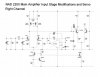
I came up with this upgrade shortly after I bought the 2200 in1984. Compared to my old amp the 2200 sounded flat, lacking in depth and transparency. So, being an audio engineer I set to work and changed the crummy caps for those mentioned above. Made all the difference. Now it sounded like it should have. I did some other mods at a later date. Replaced the input op amps with op275s. Also replaced the Class G switching diodes (S6K20) with Schottky power diodes (MBR10100). These mods got rid of a huge switching glitch when the amp went into high power mode. Now it transitions smoothly. Added four servos so the amp is now DC coupled from input to output. This solves the problem of drifting DC on the output and gets rid of some nasty distorting caps. I also redesigned some of the main amp input circuitry as they cut too many corners in order to save money. So now I have an amp which can hold its own against any amp you care to name.
 
Last edited:
That sounds awesome. I will deffinately pick your brain about those upgrades after I finish your first round. what other gear do you have upgrades for? Nad 1240 by any chance?
 
What was your thinking as to the Tantalum caps vs say Low Leakage aluminum electrolytic or film (if of small enough value)? I ask because I routinely remove the tantalum caps in rebuilds I do for those mentioned out of caution for the tantalum's somewhat spectacular failure modes and potential distortion issues, but may need to rethink this.
 
I use tantalum caps for decoupling because of their reliability and HF response and their ability to keep their capacitance, though I wouldn't use them directly in signal circuitry. Tantalum caps usually fail because the working voltage is too low for the circuitry. For instance, if you use a 10V cap in a 9V circuit then it's likely to blow. You need at least twice the working voltage. In my 30 year old CD player I replaced the electrolytics decoupling the op amps with tantalum caps which removed the harsh gritty sound. The rails are 12V and I used 50V caps. No problems for 30 years now. Same with the old 2200. I suppose that modern electrolytics are an improvement but haven't used any lately.
 
I did some major upgrades to my Sony CDP302, STR V55 and TAF45, but the only other NAD device I have is a C165 preamp which I recently acquired. It doesn't sound quite as good as my previous preamp so one of these fine days I'll get in there and make a few mods.
 
I came up with this upgrade shortly after I bought the 2200 in1984. Compared to my old amp the 2200 sounded flat, lacking in depth and transparency. So, being an audio engineer I set to work and changed the crummy caps for those mentioned above. Made all the difference. Now it sounded like it should have. I did some other mods at a later date. Replaced the input op amps with op275s. Also replaced the Class G switching diodes (S6K20) with Schottky power diodes (MBR10100). These mods got rid of a huge switching glitch when the amp went into high power mode. Now it transitions smoothly. Added four servos so the amp is now DC coupled from input to output. This solves the problem of drifting DC on the output and gets rid of some nasty distorting caps. I also redesigned some of the main amp input circuitry as they cut too many corners in order to save money. So now I have an amp which can hold its own against any amp you care to name.

With your initial list of upgrades, and those that can be found in the above quote, would you recommend the refreshing of an NAD 2200 over a new build of something like a MyRef Fremen Edition? I too have relay issues that will need some attention, just want to figure out if I should tackle these issues while it's on the bench.

Currently just driving a pair of Paul Carmody's OS MTMs, but will upgrade later. It is mated to an NAD 1155 preamp right now as well, but currently in search of a DIY alternative.
 
I've had the 2200 for 30 years now and it's working just fine. The basic design of power amps hasn't really changed in that time, so once you get an amp to work as it should then there won't be any difference between one amp and another. As you can see, the distortion is extremely low and while I could have reduced it further it wasn't worth the bother as you would never hear the difference. So if you have a 2200, it would be cheaper to instal my mods rather than get a new amp. As to relays, I've never had a problem. Never switch the amp on while you have input, particularly if you have indifferent speakers, as you will get arcing if the volume is up high enough. My speakers look pretty much like an 8 ohm resistor because i designed them that way, so that's one reason why my relays have lasted. So it's your choice in the end.
 
What would you recommend in place of polycarbonate caps? PPS?
Should I stick to service manual/stock voltage ratings?
Where did you add the 4 servos to couple DC from input to output?

That would get me as far as to your personal main circuit tweaks which I may inquire about later if you wish to share.
 
You're wasting your time and money with these mods.

A new speaker relay is mandatory, and a recap with standard electrolytic capacitors, is good maintenance, but not necessary.

Using expensive capacitors is totally unnecessary and will yield zero improvement, aside from that caused by confirmation bias.

Amplifier upgrading is a BS practice with no actual science behind it and, of course, not any sort of upgrade at all, aside from an imaginary one.

Throwing expensive parts at a circuit is an amateur approach. A professional would improve upon the actual circuit itself, with real, proven science. However, this is unncessary as hi-fi amplifiers have mostly been perfected decades ago and there's nothing more you can do. This is why there are no more innovations in audio, aside from trying to sell new junk by coming up with ridiculous lies to trick consumers.
 
Last edited:
You're wasting your time and money with these mods.

A new speaker relay is mandatory, and a recap with standard electrolytic capacitors, is good maintenance, but not necessary.

Using expensive capacitors is totally unnecessary and will yield zero improvement, aside from that caused by confirmation bias.

Amplifier upgrading is a BS practice with no actual science behind it and, of course, not any sort of upgrade at all, aside from an imaginary one.

Throwing expensive parts at a circuit is an amateur approach. A professional would improve upon the actual circuit itself, with real, proven science. However, this is unncessary as hi-fi amplifiers have mostly been perfected decades ago and there's nothing more you can do. This is why there are no more innovations in audio, aside from trying to sell new junk by coming up with ridiculous lies to trick consumers.

So repair the relay and sell it to someone who would appreciate it more? Same with preamp.
 
Last edited:
Pay no attention to Zoom - he is somewhat misguided. I used polycarbonate caps as I had some handy but polypropylene will do nicely. I added two servos from output to the first differential stage to enable DC coupling and bring the output DC to zero. The other two were round the input op amps in order to protect the main amp from any DC on the input. However, just changing the caps will give you most of the improvement. Since the maximum voltage anywhere is +/-95V , 125V caps should be OK.
 
Well, I uploaded an attachment but I don't know what happened to it. Should have mentioned that changing the input op amps to OP275 will improve things.
 
Would that be 125V all around or just the shunts? Most original caps were rated at 50, 25 or 16 V, with the odd exception of 500 and some others.

And yes, I was planning to do diodes, opamps, and the caps. I may try to tackle the servos if I can figure it out.
 
Just uploaded the attachment again. Hope it works. I suggested 125V just to be on the safe side. One cap that needs to be 125V is a 22pF polystyrene in the main amp.
 

Attachments

  • 2200mod.jpg
    2200mod.jpg
    49.3 KB · Views: 280
Back
Top Bottom