• The move to the new server is done. There are some software and database maintenance updates in process. This has us passing the hat around to help out. We appreciate any donations. Seriously, even a dollar helps. The payment page may be found here - https://www.audiokarma.org/support.html

NAD 3020 Power Switch Source???

Maybe you shouldn't have posted a 7080 question in a 3020 thread. Maybe then it would be clear for everyone...
Well that escalated quickly...

I just asked if the mentionned switch could also work for my 7080 since the 3020 is the same as the 7020 which is in the same series as the 7080. Sorry if I have offended you guys...
 
You can use Mouser part 612-P197SBEE to replace it, only trouble is they are out of stock. You should also replace the spark suppressor with one of these 539-104M06QC100.

The smaller red and white wires to the front section are either for "muting" or for a power supply discharge resistor. Neither are particularly useful, and early 3020s didn't have them anyway. NADs idea of muting was to run everything through a FED connected in the output of the preamp.

I'm currently rebuilding another 3020, and I will be adding a proper relay muting circuit to it. Watch the thread below as I'll probably post it there.

http://www.audiokarma.org/forums/showthread.php?t=460678

So I got around to getting the P197SBEE switch from mouser to replace the original switch.
I'm not completely sure how you guys wire it in and I'm not too sure when looking at the schematic.

Is it just a matter of soldering the two white wires (mains) on the two lugs of the new switch and putting the cap across the solder lugs? I believe my amp matches the x-former 4 variant. I'd have to check.
For the red and white wires, what do you guys do?
 
Last edited:
Thick wires (from the transformer and AC outlets) go to the back two terminals at the back of the switch. The two small wires (red and white) from near the headphone socket, these go on the front two terminals of the front portion of the switch.

index.php
 
Thick wires (from the transformer and AC outlets) go to the back two terminals at the back of the switch. The two small wires (red and white) from near the headphone socket, these go on the front two terminals of the front portion of the switch.

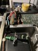
You are referring to the original switch. I'm referring to the P197SBEE switch with two terminals only (see attached picture, the switch with the green actuator).
Big white wires to either of those terminals with the cap across them. Not sure what to do with the other two wires.
 

Attachments

  • IMG_0099.JPG
    IMG_0099.JPG
    105 KB · Views: 55
Ended up just wiring up the P197SDEE switch fo the mains and left the other two wires disconnected. Works just fine and fits perfectly.
If you change the switch, make sure you change the cap as well. I went with a 0.01uf 1200v cap.
 
Back
Top Bottom