J. Schaeffer
New Member
Hello. I'm new to the forum here but not audio as a whole! It's nice to see a forum like this which seems to have very good useful information.
I have an original version nad 3020 that my father bought in the late 70's that has had no work performed on it to date. I figured it was time to go through it and do some preventative maintenance- re cap all electrolytics, replace the power switch and snubber caps, replace the speaker output terminals, re-flow the entire unit, set the dc offset and idle current, do some paint work and clean those nasty boards covered in old skotchkote which can eventually become conductive! Needless to say I have been at work for a couple weeks.
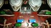
I started with the circuit board cleaning and power supply capacitors. Bought some MG chemicals safety wash and an aerosol contact cleaner. I cleaned the circuit boards with the MG and a 1" paintbrush and used the spray cleaner to rinse THAT off. I also cleaned all of the switches and pots. Worked well but took a few cleaning cycles to get things really clean. Ordered Nichicon 63 volt 2200 uF low-impedance low leakage caps for the power supply. They were the only cap in mouser's inventory that maintained the dimensions(although there is room for height) and fit the bill electrically having both low-impedance and low leakage current. The ripple current rating is 3.2A on these. Not as if THAT alone will amount to anything sonic, but I suppose it's nice to know I have it. Ordered a new alps power switch from Ebay and two 300vdc orange barrel-style 4700 pF polypropylene caps for snubbers. The amp had the classic power switch noise. Found a sato brand high quality spring terminal on Ebay and studded it to the circuit board. I know, 5-way binding posts, but I thought these were more fitting and didn't want to modify the backplane . Besides a modification to change the color ordering on the terminals, they fit perfectly requiring no modifications on lug centers and have high spring pressure. They were literally the highest-quality(the only quality)spring terminal I could find anywhere after hours of research. I have ordered a cap kit from Ebay having all 43 electrolytic caps and 6 tantalums. Have yet to install them as they haven't arrived.
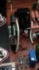
Now, on to the idle current... lol! I figured I would practice while waiting on my cap kit. I literally racked my brain on seeing 5 or more different service manuals until I found the closest one(original, A, B, I, etc.). I have the first version with the p/s caps behind the headphone jack and the phono power supply board mounted on the inside of the back plane. My amp calls for the procedure of using 1K(not 1 ohm) resistors across R653 and R654 cutting the trace under each since they're bridged(not in the procedure) with a trace, not soldered, as delivered. Next I take it you're supposed to measure across the 1K resistors with a meter for mV. I did install 25 turn 2k ohm 1/2 watt trimmers in place of both RX resistors which were factory installed with 1K and 1.2K resistors(reason for the 2K's). I installed everything and measured 215 and 179mV across the resistors. Far from the 5 to 11mV range specified. I think I followed the procedure properly but I also think the procedure may have a typo. I read the later 3020A procedure(I believe) and did ohms law a billion times trying to translate the 1 ohm(not 1K) procedure and 30 to 60mV from this later model. Through my math I believe 200mV with the first procedure equals 20mV for the later procedure with the 1 ohm(not 1K). I decided to go with it and without bridging the 1K test resistors, powered down and removed the trimmers to make sure they were not miles from the original 1 and 1.2K. Had 960 ohms on the right and 1.4K on the left trimmer as adjusted from above. I think I'll take it! Not 100% sure but it should be right. Re-installed the trimmers and folded the 1K test resistors down against the board and bridged across them with some cut off leads. I can remove them after I do the extensive re cap and final adjustment. Was able to get the offset within 0.2mV on both channels and boy are those adjusters sensitive. Almost the wrong trimmer design used in this amp altogether.
I suppose what I'm saying is I just intend to post my progress on here for everyone to see. I have some electronics experience but NO nad 3020-specific repair experience. I welcome everyone's opinions and advice as that I what i am here for, advice. I screw up too and may have missed something but there is definitely an issue with the service manual. Maybe there was an engineering revision that wasn't annotated or something on my amp. Maybe the remaining bad caps are skewing my measurements but I don't think by that much on both channels too. I noticed the main power supply rail runs a little hot, 32vdc on both sides and polarities all the way from the rectifier output to the output transistors. The print says 28vdc. The 6vac secondary to the power meter is at 7.8vac. The phono section voltages are close to print. Maybe the 32 instead of 28 volts thing is skewing my measurements also. I don't know.
Fired the amp up on some crappy speakers from an old rack stereo and it sounds real nice. Only modest but equal temps on the outputs thru the heat sink at maybe 5 watts output on the power meter for a while. Could be the speakers but the mid range sounds a little overly present. Still has a very quiet line frequency hum thru any of the outputs in any configuration, the reason for all this work. Lol! Forgot to mention that...
It does the hum thing (which is quiet, maybe 5db) no matter if the pre amp is coupled, uncoupled, through the headphones and speakers, and no matter what switch configuration is used with either previous combination. So hopefully this 49 capacitor kit does the trick! The caps are at least 40 years old now!
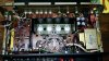
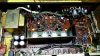

I have an original version nad 3020 that my father bought in the late 70's that has had no work performed on it to date. I figured it was time to go through it and do some preventative maintenance- re cap all electrolytics, replace the power switch and snubber caps, replace the speaker output terminals, re-flow the entire unit, set the dc offset and idle current, do some paint work and clean those nasty boards covered in old skotchkote which can eventually become conductive! Needless to say I have been at work for a couple weeks.
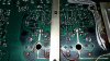
I started with the circuit board cleaning and power supply capacitors. Bought some MG chemicals safety wash and an aerosol contact cleaner. I cleaned the circuit boards with the MG and a 1" paintbrush and used the spray cleaner to rinse THAT off. I also cleaned all of the switches and pots. Worked well but took a few cleaning cycles to get things really clean. Ordered Nichicon 63 volt 2200 uF low-impedance low leakage caps for the power supply. They were the only cap in mouser's inventory that maintained the dimensions(although there is room for height) and fit the bill electrically having both low-impedance and low leakage current. The ripple current rating is 3.2A on these. Not as if THAT alone will amount to anything sonic, but I suppose it's nice to know I have it. Ordered a new alps power switch from Ebay and two 300vdc orange barrel-style 4700 pF polypropylene caps for snubbers. The amp had the classic power switch noise. Found a sato brand high quality spring terminal on Ebay and studded it to the circuit board. I know, 5-way binding posts, but I thought these were more fitting and didn't want to modify the backplane . Besides a modification to change the color ordering on the terminals, they fit perfectly requiring no modifications on lug centers and have high spring pressure. They were literally the highest-quality(the only quality)spring terminal I could find anywhere after hours of research. I have ordered a cap kit from Ebay having all 43 electrolytic caps and 6 tantalums. Have yet to install them as they haven't arrived.
Now, on to the idle current... lol! I figured I would practice while waiting on my cap kit. I literally racked my brain on seeing 5 or more different service manuals until I found the closest one(original, A, B, I, etc.). I have the first version with the p/s caps behind the headphone jack and the phono power supply board mounted on the inside of the back plane. My amp calls for the procedure of using 1K(not 1 ohm) resistors across R653 and R654 cutting the trace under each since they're bridged(not in the procedure) with a trace, not soldered, as delivered. Next I take it you're supposed to measure across the 1K resistors with a meter for mV. I did install 25 turn 2k ohm 1/2 watt trimmers in place of both RX resistors which were factory installed with 1K and 1.2K resistors(reason for the 2K's). I installed everything and measured 215 and 179mV across the resistors. Far from the 5 to 11mV range specified. I think I followed the procedure properly but I also think the procedure may have a typo. I read the later 3020A procedure(I believe) and did ohms law a billion times trying to translate the 1 ohm(not 1K) procedure and 30 to 60mV from this later model. Through my math I believe 200mV with the first procedure equals 20mV for the later procedure with the 1 ohm(not 1K). I decided to go with it and without bridging the 1K test resistors, powered down and removed the trimmers to make sure they were not miles from the original 1 and 1.2K. Had 960 ohms on the right and 1.4K on the left trimmer as adjusted from above. I think I'll take it! Not 100% sure but it should be right. Re-installed the trimmers and folded the 1K test resistors down against the board and bridged across them with some cut off leads. I can remove them after I do the extensive re cap and final adjustment. Was able to get the offset within 0.2mV on both channels and boy are those adjusters sensitive. Almost the wrong trimmer design used in this amp altogether.
I suppose what I'm saying is I just intend to post my progress on here for everyone to see. I have some electronics experience but NO nad 3020-specific repair experience. I welcome everyone's opinions and advice as that I what i am here for, advice. I screw up too and may have missed something but there is definitely an issue with the service manual. Maybe there was an engineering revision that wasn't annotated or something on my amp. Maybe the remaining bad caps are skewing my measurements but I don't think by that much on both channels too. I noticed the main power supply rail runs a little hot, 32vdc on both sides and polarities all the way from the rectifier output to the output transistors. The print says 28vdc. The 6vac secondary to the power meter is at 7.8vac. The phono section voltages are close to print. Maybe the 32 instead of 28 volts thing is skewing my measurements also. I don't know.
Fired the amp up on some crappy speakers from an old rack stereo and it sounds real nice. Only modest but equal temps on the outputs thru the heat sink at maybe 5 watts output on the power meter for a while. Could be the speakers but the mid range sounds a little overly present. Still has a very quiet line frequency hum thru any of the outputs in any configuration, the reason for all this work. Lol! Forgot to mention that...
It does the hum thing (which is quiet, maybe 5db) no matter if the pre amp is coupled, uncoupled, through the headphones and speakers, and no matter what switch configuration is used with either previous combination. So hopefully this 49 capacitor kit does the trick! The caps are at least 40 years old now!
Last edited: