• The move to the new server is done. There are some software and database maintenance updates in process. This has us passing the hat around to help out. We appreciate any donations. Seriously, even a dollar helps. The payment page may be found here - https://www.audiokarma.org/support.html

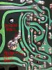
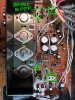
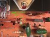
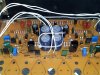
Nad 3020 work including idle current adjustment

I've been working on it every night a few hours since I last posted. Ended up I did hurt something... I hadn't performed a sonic test due to the fact I was able to turn the trimmers back the amount of turns I had gone and the offset was good. Ended up that it had a 60/120 hz buzz that was consistent with the volume knob. It only occurred with an input adapter wire was connected and that input seletcted, and would disappear when an input device was connected and actually driving the amp's input. Therefore, as soon as the music started the noise disappeared. Otherwise the amplifier performance was great. Removed and replaced all solder in the amp . Did b/e voltage drop tests on all 40 or so transistors in the amp with it powered up. All units 550 to 620 mV. What the heck? Makes sense since the offset was good, right? Started testing all caps and trans out of circuit last night. All good. Resistors... all good, except the 47k resistor coupling the phono thumbscrew ground. Found it last, of course after 30 hours of work. It didn't even appear damaged but was open. I can't believe it took this long to find it. Lack of experience with this or any amp repair the likely culprit. I knew it was a ground loop because the sound, so I read, and I had 150mV ripple everywhere in any dc supply line reading ac on a meter. I back probed the headphone jack and discovered that this stray ac voltage was varying with the volume knob also.
In the meantime I have all diodes except the zeners coming tomorrow. I figured I'd do them anyway since this has become a full restoration. Was able to get the output cans out without damaging the mica wafers under them and the bd 139s. I ordered the to-3 mount pads that Leesonic has used on at least one of his amps that I know of. Also, this amp has the 6553/6556 complimentary pairs in front of the outputs. Probably routine but differs from the schematic.
Hopefully this is the only problem since I over biased the amp, and I suppose if one transistor turns on full that means they all turn on full because of overdriving the feed back loop, etc. Everything theoretically went dc and I don't think that was great for the amp. I'm glad all the original transistors are good in the amp, I suppose that's where the sonic magic is. I know nothing about tuning and matching small signal transistors and the modern replacements seem to vary on their specifications.
As far as the idle current, I certainly have it back to stock 1k and 1.2k except it's across trimmers now. Maybe I'll get brave enough to dial it in at some point the right way now that I know how.
I'll have it wrapped up by this weekend and let you guys know if it's fixed. Thank you for the wisdom so far.

Edit- I am not sure if what I said is what really happened since I don't have any real test equipment and lack long-time experience.
 
Last edited:
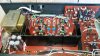
The amplifier is finished for now! Still has all original transistors. Built a dbt with a lamp cord and a small base bulb socket with a loop for current readings. I fired the amp up on this with a 15 and 40 watt bulb... powered it up thru the dbt and checked for ac and dc on the speaker terminals with the horseshoes out. Yep, left channel negative 1 volt dc offset while the right was at zero. Switching the positions of the 6553 and 6556 pair on the left channel will do that! Dang, I sure am glad I followed some advice on the dbt! So as a summary I recapped the electrolytics, new power switch and snubbers, replaced the tantalums, all the baw62 diodes changed, the 1n4002's in the other power supply changed, the kbl02 changed, installed trimmers, new tim under the to3's, replaced all the solder, did some wire management and straightened all the components. All the original diodes tested good but at less than 5 dollars for everything I did it anyway. I will try the idle current adjustment again at a later date. Its been a job for sure!
20190317_115755.jpg
Another edit! The final idling current draw measurement on the ac mains going into the amplifier is exactly 50 mA powered up, of course.
 
Last edited:
I've had one of these on the bench where a couple of the mica washers under the main transistors had fallen apart, causing their contact with the heatsink and blowing fuses. If i got another one of these to work on, I would replace those as a matter of course.

Im not sure if this is a common fault or not, but that issue came up in a couple of internet searches, so it was the first thing I looked at
 
I tried asking this question in a new thread with no luck so I'll give it a try here. I'm a new member and just recapped an NAD 3020 that I bought new in 1982. This is a later version with the large caps in the center of board behind the heat sink. The recap seems to have gone well and startup and other noises have all disappeared. The amp sounds great though I haven't given it a lot of listening time yet. My questions: Is it 100% necessary to reset the idle current after a recap? At idle the transistors get warm but not hot. The DC offset is 28.4 mV left and 13.3 mV right. Are those acceptable numbers? Finally, if idle adjustment is necessary I plan to add the adjustable resistors per other threads I've seen here. However, I'm not clear if I am identifying the solder bridge correctly and where to measure across. I've attached a couple photos, does it look like I'm understanding this correctly? Thanks!
 

Attachments

  • IMG_7799.jpg
    IMG_7799.jpg
    158.5 KB · Views: 43
  • IMG_7800.jpg
    IMG_7800.jpg
    176.8 KB · Views: 43
  • IMG_7801.jpg
    IMG_7801.jpg
    124.6 KB · Views: 40
Is it 100% necessary to reset the idle current after a recap?
In some cases, while it may not be absolutely necessary, frankly for the minimal extra work involved I always at least check them, for peace of mind if nothing else.

For your 3020 - to check them, you simply need to remove the solder shorts ('bridge') that you've correctly identified in your first photo, one for each channel, and measure the idle currents as voltage drops across the R653 (Left) or R654 (Right) resistors (both should be 1R, but check).
Set all tone controls centred, volume to zero, and with no inputs or speakers connected, attach your DMM (ideally using mini-grabber leads) to measure mV across the R653 resistor, so one lead on each side of R653. Turn the amp on, and monitor the idle current via the voltage drop on your DMM - be sure to keep monitoring for at least 30 - 60 minutes, as the amp warms up. Note: the mV reading will increase as it warms up, probably overshoot a bit, before correcting itself, and slowly settling to its final value. You're looking for ca. 30mV drop across R653, within a +/- 10mV range (so 20 - 40mV).

If your idle current is already set within that range, then you could just replace the solder short, and leave the existing fixed resistor (RX1) as it is. There's nothing magical about fitting adjustable trimmers to set bias, or setting the idle to exactly 30.00mA, they just make setting-up a lot easier - in the past, and even today, fixed resistors were often used to provide more reliability.

If your idle currents do need adjusting, then the positions you've indicated are indeed where I install the relevant trimmers.

20130616_162756.jpg

If you don't have mini-grabber leads, I'd suggest to use Leesonic's approach, and solder extension wires to the relevant points (e.g., each side of the solder bridge you just removed), so you can measure safely with normal probes well away from the amp pcb. A second DMM also saves a lot of time, so you can do both channels at the same time. Note - any mistakes or shorts you might make with a slipped probe while measuring the idle currents can be an painful lesson.... and a lot more work.

The DC offset is 28.4 mV left and 13.3 mV right. Are those acceptable numbers?
Both of those values are within the 0V +/-50mV spec. range, and shouldn't be any problem.

There are open-frame trimmers (in your 2nd photo) to adjust DC-offsets if wanted - the originals can sometimes be cleaned, but after 40 years service its' probably earned itself some new ones !
 
Last edited:
Awesome, thank you Goldie99! That was exactly the info I was looking for. I'm guessing you meant 1k resistors, not 1R?
 
R653 & R654 should be 1 Ohm resistors, not 1k - check the colour bands on them.
They are only in circuit while the solder shorts are removed and the idle currents are being set. Otherwise, once you put the solder shorts back, they are literally 'shorted' out of the circuit again.

Don't forget to put the shorts back as soon as you've finished setting the idle currents - the amp shouldn't be 'used' without the shorts being replaced.
 
Here's a pic of the resurrected 3020 Series 20. It's so great to be listening to this old amp again.

IMG_7816 edited.jpg
 
Last edited:
Looks good. One point to watch with that version (among others) is C531, it's a 47uF / 63V electrolytic in the manual - it's better to go for a 47uF / 100V rated cap. It's the cap in your muting circuit that looks like it was leaking before your recap (it might also be worth cleaning a bit more where it leaked - to avoid future corrosion issues).

IMG_7800.jpg
 
Good to know, thank you. Would that explain the loud pop I was getting when I engaged the mute prior to the recap?

I assumed that was glue and scraped it all off but it left a dark stain on the board which I could not remove.
 
Would that explain the loud pop I was getting when I engaged the mute prior to the recap?

No, C531 is part of the automatic start-up / shut-down muting, intended to avoid start-up & shut-down noises. The 'mute button' is a separate straightforward switch in the pre-amp, that just shunts most of the audio signal to ground, that may well have been affected by other failing caps, but not C531 per se.
 
Got it. Maybe responsible for the loud buzz/hum on startup then? (which is now gone)

Your knowledge is appreciated. This isn't something I do on a regular basis.
 
Goldie 99, you were correct about C531. It was way out of spec. Just for fun I tested all the caps that I pulled. Out of 51, 4 were bad. Roughly an 8% failure rate. And that was just capacitance. I wasn't able to check ESR.
 
Last edited:
No surprise really, if you put a DC voltmeter across C531 you should see why - it was / is under-rated @ 63V.
If you'd checked ESR as well, you'd probably have found a few more failing, but after ca. 40 yrs, once any initial fault tracing has been completed, a full recap is the best option for these.
 
Nice to see so many NADs here, im starting my NAD 3020e project
need advise on report i got from specialist who quoted half a thousand for repair job !
From report:
The left channel has a 1200mV dc offset. This is becuase the NPN driver is leaking across its base emitter junction
 
It's sounds a simple as replacing that transistor and then resetting the bias and dc offset, but the experts on here may have better information. There could be other related issues. You may want to start a new thread with all the specifics from the report and a photo of the inside of your 3020e.
 
Last edited:
Back
Top Bottom