• The move to the new server is done. There are some software and database maintenance updates in process. This has us passing the hat around to help out. We appreciate any donations. Seriously, even a dollar helps. The payment page may be found here - https://www.audiokarma.org/support.html

NAD 3020A

resoglas

New Member
Hello, AK,

I am new here as I am also new in electronics. Last month I got myself a Thorens TD150 MK1, a couple of KEF Q100s and as the title tells the NAD 3020A. This is my first audio related project. I have been researching on it for quite a while but there are still some things I can not find or can not solve by myself so I am asking for some guidance.

  • Power switch.
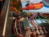
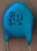
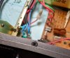
    • As per recommendations in other threads I chose the C&K NE1839EE switch with 104M06QC100 for spark suppression but the problem is that the current switch has two capacitors (my guess is because its EU version and the wiring is different)
    • IMG_20190914_135007.jpg IMG_20190915_133106_3.jpg
    • Should I also install two of 104M06QC100s ?
  • Power transistors.
    • Currently there are two 2N3055 (Q8310) and two MJ2955 (Q8315) transistors. There were people suggesting to switch these to MJ15003(G) and MJ15004(G) but the threads suggesting these are 5-10 years old. Are these still an option or would you suggest something else? I will also need 4x (I think) 3W 0.33ohm emitter resistors. I have found these RWM0410R330JR15E1 but I'm not entirely sure how or should I rather say where to exactly install them.
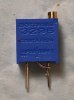
  • I will replace VR5 and VR6 with Bourns 20Kohms (3296Y-1-203LF) resistors for DC offset alignment
  • I will also take 2x Bourns 1Kohms (3296Y-1-102LF) with LR1F1K2 and MF1/4DC1R00F for Bias adjustment (found leesonic recommending almost all of the above)
  • This is the complete list of electrolytic capacitors I have found installed https://gist.github.com/resoglas/9776b4c59dc283317045dc7d36e1002f I will replace all of these to the Panasonic FCs and Nichicon (same values) with an exception for 0.68uF 25V as I was unable to find these, I chose Nichicon UKL2AR68KDD 0.68uF 100V and for 1uF 25V I chose Nichicon UMF1V010MDD1TP 1uF 35V.
  • I will replace Cartridge Fuses with 2x 0218004.MXP and 2x 0218001.MXP
  • The complete Mouser cart can be found here https://eu.mouser.com/ProjectManager/ProjectDetail.aspx?AccessID=16a707e7e4 Quantities will change I just want not to forget something
  • I will most probably want to change the driver (?) transistors that sit on a heat sink, D669A and others in between of 2200uF caps and power transistors, or should I not?
Any advice, comment or insight on improving my humble task list is accepted and welcome!

I know I should most probably lend this restoration to a professional but the idea of restoring it myself keeps a hold of me. I am not entirely sure by now how did it occur to me at all or developed itself into a hobby, but I am determined to do it myself even though / if I will fail at some point.

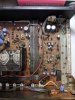
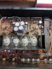
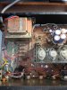
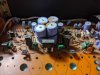
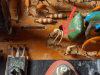
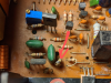
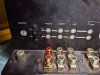
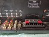
Some dirty photos:
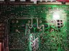
IMG_20190912_210303.jpg IMG_20190825_232114.jpg IMG_20190825_232122.jpg IMG_20190825_232132.jpg IMG_20190912_205813.jpg IMG_20190915_133645.jpg
 
Last edited:
Register to hide this ad
Are you replacing output transistors from necessity or just because?

Wholesale electrolytic capacitor replacement I can understand but why go beyond that unless due to actual component failure?

There’s nothing wrong with a 3020 in (restored) stock form and attempting to squeeze more “performance” out of it will likely not be audible. Therefore a waste of time, money and open the door to a potential mishap which seems to concern you.

Looks like you've got a nice, sensible system underway
 
A NAD 3020A (virtually identical to yours) was the first amp I ever completely stripped and rebuilt, very similar to what you're proposing - done slowly, carefully, and as a (major) learning exercise it was a very rewarding rebuild, that I still use often. I'd say the 'key' was very much in patience, taking the time to get it right, and studying it as I went along...

I agree generally with 62Vauxhall's comments, in that I'd focus first on fault-finding and getting the amp working - once you've resolved the problems, or at least identified them, recapping and selective upgrading, should be straightforward. Keep your eyes open for dry & damaged solder joints, they're quite common with NAD 3020's now, but are usually easily repaired (leaded solder, not lead-free). I note from your last photo that the outputs have been removed... hopefully after already checking the amp for faults ?

A couple of comments to the choices:

Power switch - I'd at least initially keep the original switch unless you know it to be faulty. With the higher European voltages, they tend to 'survive' better than the USA versions in my experience. If you change the caps on the mains switch, you should use two, and they must be suitably mains rated, according to the country you're in - I'm assuming you got the amp in the same 'region', e.g., you're in Europe, and bought it in Europe.

Output transistors, unless they're blown, I'd just clean & reuse them. The '8310' and '8315' references are probably date references from when they were made - weeks 10 & 15, 1983 - so they're likely to be the original outputs. If you keep them, there's no need to fit extra emitter resistors. Other transistors - again, unless they're faulty, I'd keep as is.

Caps - I didn't check all your list, but there should be one cap that's originally a 63V grade - change that one for a 100V grade (FC is fine), the original is under-spec'ed and often fails. Some of the smaller, e.g., 1uF, signal path caps can also be changed to films, e.g., Wima MKS2 or similar (watch out for lead spacings, lead length, & cap dimensions).

Trimmers - good choices, and well worth upgrading.

Finally, have fun with it, and welcome to AK !
 
Thanks for your response, 62vauxhall!

My first intention was indeed keeping the NAD stock but recapped. I believe it would work just fine but this belief is mainly based on the fact that it powers on as I haven't actually tested it out in any other more reasonable way. One other criteria though is local availability of the parts. I can only get caps, transistors and other components that are of any quality via Mouser, Digikey or Fernell, so the caps alone don't cover the free shipping price (shipping alone would be 20€ / $20), which left me in a situation of deciding what else could I restore/upgrade. So basically because of this, my list consists of incoherent thoughts that I caught up along the way.
 
A NAD 3020A (virtually identical to yours) was the first amp I ever completely stripped and rebuilt, very similar to what you're proposing - done slowly, carefully, and as a (major) learning exercise it was a very rewarding rebuild, that I still use often. I'd say the 'key' was very much in patience, taking the time to get it right, and studying it as I went along...

I agree generally with 62Vauxhall's comments, in that I'd focus first on fault-finding and getting the amp working - once you've resolved the problems, or at least identified them, recapping and selective upgrading, should be straightforward. Keep your eyes open for dry & damaged solder joints, they're quite common with NAD 3020's now, but are usually easily repaired (leaded solder, not lead-free). I note from your last photo that the outputs have been removed... hopefully after already checking the amp for faults ?

A couple of comments to the choices:

Power switch - I'd at least initially keep the original switch unless you know it to be faulty. With the higher European voltages, they tend to 'survive' better than the USA versions in my experience. If you change the caps on the mains switch, you should use two, and they must be suitably mains rated, according to the country you're in - I'm assuming you got the amp in the same 'region', e.g., you're in Europe, and bought it in Europe.

Output transistors, unless they're blown, I'd just clean & reuse them. The '8310' and '8315' references are probably date references from when they were made - weeks 10 & 15, 1983 - so they're likely to be the original outputs. If you keep them, there's no need to fit extra emitter resistors. Other transistors - again, unless they're faulty, I'd keep as is.

Caps - I didn't check all your list, but there should be one cap that's originally a 63V grade - change that one for a 100V grade (FC is fine), the original is under-spec'ed and often fails. Some of the smaller, e.g., 1uF, signal path caps can also be changed to films, e.g., Wima MKS2 or similar (watch out for lead spacings, lead length, & cap dimensions).

Trimmers - good choices, and well worth upgrading.

Finally, have fun with it, and welcome to AK !

Thank you for such a detailed answer. I really appreciate it.

Both of your and 62vauxhall comments sound very rational. I reconsidered to not touch any transistors, well unless I find them faulty in some way. I will not bother you with questioning on how to test them as I'm sure I will find plenty of threads here in AK on that topic.

You mentioned that patience was the key in your rebuild process.. Yeah, about that.. The fact that the outputs are removed now is the result of me acting the exact opposite - I felt the urge to clean the amp ASAP and so I rushed on some things before time and before thinking too much.

Indeed I and the amp are from Europe. Would you be so kind and recommend some caps for the mains switch? Removing the transistors (that is if they are OK) from the order would make me ~10€ short to be eligible for free shipping so I am still thinking of replacing the switch with caps.

I think Im getting on the right path towards restoring the amp thanks to both of you. At least my main concerns are suppressed for now. I will keep the thread up to date as I believe there are not that many info related to the 3020A specifically. I couldn't even find a service manual for this specific model and the fact that the 3020B is very similar does not add much confidence.
 
Last edited:
resoglas Welcome to AK. Good luck with the 3020a. From what I heard use the 3020b schematic I think. But check your parts. NAD did a lot of upgrades/changes that sometimes didn't get documented right. See you checked leesonic's rebuild threads. AK's leading man on NAD rebuilds. Like his idea of replacing E-caps lower than 4.7 mfd with film caps (WIMA). Have a 3140 myself.
Check out this site.https://www.vintageshifi.com/repertoire-pdf/Nad.php Not a bad source for information. I figure you found HifiEngine.com. https://www.hifiengine.com/manual_library/nad/3020.shtml. electrotanya.com is good too.
 
It's unfortunate you didn't test the amp more fully before starting, but there's a simple DMM test you can use to check the outputs, and other transistors, out of circuit - https://audiokarma.org/forums/index.php?threads/bipolar-junction-transistor-testing-basics.43186/

For the switch caps, I'd use these in UK - https://www.mouser.co.uk/ProductDetail/?qs=kqlpaQXGN233/6nkfET8bA== I can't comment for other EU countries (regs. may or may not be different, I'd guess not, but I don't know).

When I started I had similar problems with parts shipping costs - I used the following to pad the first few orders - https://www.mouser.co.uk/ProductDetail/Pomona-Electronics/3782-48-2?qs=/ha2pyFadugpftiXWYERGr/bF2E66s411ERJkflJN2IgYowAsHct/Q== - they can save a lot of potential problems... and are invaluable when setting up bias etc.

You're right, there is no single 3020A service manual that I've ever found, but the 3020B is close for most of it, and parts of the earlier 3020 manual are close for other parts. I have detailed notes from a couple of 'A' versions if you do get stuck. NAD made a lot of changes 'on the fly' as the model evolved from 3020, to 3020A, to 3020B, etc., so watch for the exact part values installed in your amp, not what's shown in the manual part lists or schematics, they may not be the same (what's physically there will be correct, if it's never been repaired).
 
Currently there are two 2N3055 (Q8310) and two MJ2955 (Q8315) transistors. There were people suggesting to switch these to MJ15003(G) and MJ15004(G) but the threads suggesting these are 5-10 years old.

People suggesting changing the venerable 3055/2955 to the 15003/4 really have no idea what they are talking about.

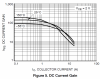
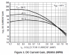
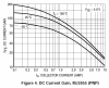
The lower gain characteristics at lower drive would mean the amplifier would likely perform considerably worse due if you were to replace them. Leave them well alone. They have more than enough SOA for the little 3020A.

15003:
upload_2019-9-17_18-38-14.png

15004:
upload_2019-9-17_18-38-48.png

3055:
upload_2019-9-17_18-39-43.png

2955:
upload_2019-9-17_18-40-13.png
 
Last edited:
Thanks for the replies. I have replaced all of the electrolytic caps yesterday and then I saw that the Bourns 20K trimmers are way smaller than the original VR5/VR6 trimmers. How should I extend the leads to reach the holes? With some wire or..?

Thanks, resoglas
 
If you're careful, you can get away with extending only the middle leg - I just use a length of lead cut off from another component.
 

Attachments

  • 913849935.png
    913849935.png
    725.2 KB · Views: 63
Last edited:
You can either (gently) bend the centre lead of the trimmer over to one of the end leads, loop it around the end lead to 'secure' it, solder it, and trim any excess - that should leave you with the trimmer having just the 2 end leads. Keep the bent lead, & soldering, as close as possible to the trimmer body, so it will still 'sit' tidily on the main pcb once installed.

... or, just use a short length of cut-off component lead to solder between one end lead and the centre lead of the trimmer (avoids bending and possibly breaking the centre trimmer lead).

Modified like that, the trimmer is just a variable resistor - try it just before soldering it, and you'll see how it works.
 
You can either (gently) bend the centre lead of the trimmer over to one of the end leads, loop it around the end lead to 'secure' it, solder it, and trim any excess - that should leave you with the trimmer having just the 2 end leads. Keep the bent lead, & soldering, as close as possible to the trimmer body, so it will still 'sit' tidily on the main pcb once installed.

... or, just use a short length of cut-off component lead to solder between one end lead and the centre lead of the trimmer (avoids bending and possibly breaking the centre trimmer lead).

Modified like that, the trimmer is just a variable resistor - try it just before soldering it, and you'll see how it works.
Thanks, I may have rushed a little with the question as I have found the answer on Google pretty fast myself, sorry!

These trimmers were the last parts that I have installed! Now I am waiting for fuse clips/holders to come (luckily found some relatively cheap on Amazon) as the old ones were rusty by the PCB and two of them broke while replacing fuses. Overall the NAD is in pretty "sad" shape with some rust here and there and also the front panel is a little broken by every screw. But hopefuly I will be able to restore it to a solid shine with time.

IMG_20190929_214333~2.jpg IMG_20190929_214451.jpg IMG_20190929_214506.jpg
 
Hello again,

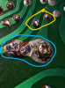
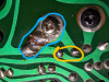
I have powered on the amp for the first time yesterday and it sounded great with just a tiny hum after pressing the power on switch. I have managed to set the DC offsets to 0, but as for the bias I found my self lost in where to place the DMM for measuring. I have unsoldered the massive blob as show in the picture (blue is the bridge, yellow is the resistor).

389034381.png 1965665538.png

Do I measure DC across the yellow resistors or
across the bridge? Thanks!
 
If you look at the pcb traces on the 2 'sides' of the solder bridges you've removed, you'll see that one side of the solder bridge 'tracks' directly to one end of the resistor, while the other side of the solder bridge 'tracks' directly to the other end of the same resistor, that's why it's called a soldershort in the manual; the solder 'blob', when it's in place and bridging both sides is simply 'shorting' the resistor, so it's no longer part of the circuit.... so the answer to your question is simply, either, they're both the same.

If you have mini-grabber leads for your DMM, you can just clip them onto the resistor legs on top of the pcb (with the solder bridge removed), and measure the mV drop across the relevant resistor. They should be 1R resistors, so 1mV drop is equivalent to 1mA bias current (spec. setting is 30mV after warm-up).

Alternatively, if you don't have mini-grabber leads, the easiest is probably to just solder a couple of thin 'extension wires' from the 2 sides of the removed solder bridge, so you can clip your DMM onto them further away from the pcb / amp (so there's less risk of shorting anything). Measurement and adjustment would otherwise be identical.

It's possible to preliminarily set bias while the unit is connected to a DBT, but the final setting should be done with normal mains power connected, without DBT, and last, but not least, don't forget to replace the solder bridges after you've set the bias currents...

Question - where did you source the replacement RCA / Phono sockets in your photos above ?
 
If you look at the pcb traces on the 2 'sides' of the solder bridges you've removed, you'll see that one side of the solder bridge 'tracks' directly to one end of the resistor, while the other side of the solder bridge 'tracks' directly to the other end of the same resistor, that's why it's called a soldershort in the manual; the solder 'blob', when it's in place and bridging both sides is simply 'shorting' the resistor, so it's no longer part of the circuit.... so the answer to your question is simply, either, they're both the same.

If you have mini-grabber leads for your DMM, you can just clip them onto the resistor legs on top of the pcb (with the solder bridge removed), and measure the mV drop across the relevant resistor. They should be 1R resistors, so 1mV drop is equivalent to 1mA bias current (spec. setting is 30mV after warm-up).

Alternatively, if you don't have mini-grabber leads, the easiest is probably to just solder a couple of thin 'extension wires' from the 2 sides of the removed solder bridge, so you can clip your DMM onto them further away from the pcb / amp (so there's less risk of shorting anything). Measurement and adjustment would otherwise be identical.

It's possible to preliminarily set bias while the unit is connected to a DBT, but the final setting should be done with normal mains power connected, without DBT, and last, but not least, don't forget to replace the solder bridges after you've set the bias currents...

Question - where did you source the replacement RCA / Phono sockets in your photos above ?

Roger, thanks! Yes, the previous resistors were replaced with 1ohm 1% 100PPM ones, I just couldn't get any voltage reading while measuring the solder joints on them and I suppose it would make sense for someone with more knowledge, it did not for me :D

The RCA sockets are https://eu.mouser.com/ProductDetail/161-R239A2-E . These were the only ones I could find after a looong scrolling at Mouser.

One more question before I short something out - the negative (-) lead of DMM goes on the side with a screw as far as I understand?
 
One more question before I short something out - the negative (-) lead of DMM goes on the side with a screw as far as I understand?

It makes little difference, but the 'clearest' is probably if you indeed put the -ve lead on the side where the screw goes, then your DMM measurement will be a positive mV drop across the resistor. It works either way though, the number is important not the +/- indication.

If you were trying to measure before completely removing the solder bridges then you wouldn't get any meaningful measurement on them at all - otherwise, if you have 25 turn trimmers, 25 turns can be a looong way from where it needs to be (you can always pre-set them approximately on the DBT, back them off, then final set them without DBT).

Thanks for the RCA sockets link - they look like a good fit, but not cheap.
 
It makes little difference, but the 'clearest' is probably if you indeed put the -ve lead on the side where the screw goes, then your DMM measurement will be a positive mV drop across the resistor. It works either way though, the number is important not the +/- indication.

If you were trying to measure before completely removing the solder bridges then you wouldn't get any meaningful measurement on them at all - otherwise, if you have 25 turn trimmers, 25 turns can be a looong way from where it needs to be (you can always pre-set them approximately on the DBT, back them off, then final set them without DBT).

Thanks for the RCA sockets link - they look like a good fit, but not cheap.
So if lets say I am getting 0 mV shown in the DMM even after extending bridges with wires, does that mean that my trimmers are way off to one side or that there is a problem somewhere else (something shorting)? I've cleaned the bridges with isopropol and there is clearly a gap between them.

The RCA sockets indeed fit perfectly but are pricey compared to other components in the list. I guess the price comes from the fact that its a rare (an assumption) layout of pins now
 
0mV would mean there's no current flowing through the resistor - a couple of checks:
- is the DMM correctly set for DC mV measurement ?
- with the unit off, does the resistor measure ca. 1 Ohm ?

If both are yes, then the trimmer is probably a long way off.
 
Back
Top Bottom