• The move to the new server is done. There are some software and database maintenance updates in process. This has us passing the hat around to help out. We appreciate any donations. Seriously, even a dollar helps. The payment page may be found here - https://www.audiokarma.org/support.html

NAD 3140 Output and Preamp(?) Problems

Thorbr

Active Member
Hello,
First post so excuse any jitters. Picked up subject amp this week. Based on preliminary tests, determined that RH amp output channel is shot. OK, no issue output transistors are readily available. On further testing using a function generator on Aux/Tuner/Tape inputs and scope on the preamp RH channel output (Jumper removed), it appears that RH channel preamp output is also not functional. What is throwing me off, is with headphones plugged in and audio source at same inputs, I get sound through both channels. Not sure how that can be, as I get no RH Channel signal from the preamp output, which would normally be plugged in, via jumper, to the amp input section. Any thoughts on this? Thanks in advance for any feedback.
 
Register to hide this ad
On my NAD 317 the headphones have a separate power supply. and plugging them in activates the mute relay for the main amp.
 
Goldie99, No, not in bridged mode. There is a small PB in the back, that by default is held in by a screw with tab, for 2 channel stereo function. Thanks
 
On my NAD 317 the headphones have a separate power supply. and plugging them in activates the mute relay for the main amp.
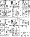
Screenshot of the headphone jack circuit attached. Appears to be the same circuit as for speakers.
 

Attachments

  • Screenshot 2024-08-25 154918.jpg
    Screenshot 2024-08-25 154918.jpg
    176.6 KB · Views: 31
Audio through headphones suggests a measurement error, yes headphones comes off the spkr line which means the R-preamp must be working. You may have a dirty spkr selector, try connecting to/selecting spkr set B. Also check for audio before the spkr selector, eg, at the emitter resistors
 
Audio through headphones suggests a measurement error, yes headphones comes off the spkr line which means the R-preamp must be working. You may have a dirty spkr selector, try connecting to/selecting spkr set B. Also check for audio before the spkr selector, eg, at the emitter resistors
Selected A and B speakers previously with same result. Will test at emitter resistors. Thanks
 
Read that in another NAD related post, but I do not see these on the circuit board or schematic. Will recheck. Thanks
For headphone jacks that do not have a separate power supply, the jack itself can have switches built in it to cut signal to speakers when headphones are plugged in ( see pic), but based on the schematic that is not the case. Try emailing NAD support and see what they say. Maybe the schematic is not complete.
 

Attachments

  • IMG_9497.png
    IMG_9497.png
    297.9 KB · Views: 5
It looks like CURRENT RELAYS TB1 and TB2 are connected to headphone jack L+R channels, as are SPK A and B for both channels.

I am guessing those relays are closed when speakers are the output, due to the powering of the L601/L602 coils, and with low power headphone as the output the relays are open due to not enough power going through the coils to close the relays.
 
Last edited:
The 3140 does not have any switches, or relays, controlling audio to the headphones socket, the audio signal to headphones is always active. TB1 & 2 are 'thermal breakers', as a different form of amp 'protection' to the more familiar output relay approach.

I'm with mbz - check with the scope for audio directly at the amp output, e.g. going into TB1 & 2, and take it from there.
 
The 3140 does not have any switches, or relays, controlling audio to the headphones socket, the audio signal to headphones is always active. TB1 & 2 are 'thermal breakers', as a different form of amp 'protection' to the more familiar output relay approach.

I'm with mbz - check with the scope for audio directly at the amp output, e.g. going into TB1 & 2, and take it from there.
So how does it cut the signal to the speakers when the headphones are plugged in? Or do you think the speakers are supposed to be active when headphones are plugged in?

And I have to disagree with you, since TB1 is labeled as "CURRENT RELAY", why would they call it a relay if it was not?, and they both have a coil to activate them just like any other relay.
 
So how does it cut the signal to the speakers when the headphones are plugged in? Or do you think the speakers are supposed to be active when headphones are plugged in?

No offense, but as I said before, the headphones socket is always active. If you want to listen to phones only, you turn the speakers off... it's all explained in the manual, that nobody seems to bother to read these days.

And I have to disagree with you, since TB1 is labeled as "CURRENT RELAY", why would they call it a relay if it was not?, and they both have a coil to activate them just like any other relay.

You'd have to ask NAD why they call them 'current relays' - I can only presume it's because they are thermal breakers that 'open' when there's too much current for too long (= too much heat). The same breakers are used in the 3020.

I can assure you they are not relays, and they certainly don't have coils driving them. Where do you see coils driving them ?
 
The 3140 does not have any switches, or relays, controlling audio to the headphones socket, the audio signal to headphones is always active. TB1 & 2 are 'thermal breakers', as a different form of amp 'protection' to the more familiar output relay approach.

I'm with mbz - check with the scope for audio directly at the amp output, e.g. going into TB1 & 2, and take it from there.
Headphone jack function confirmed. Thank you. So I think my preamp section is fine. In regards to the amp, I set the DC off-set and it is stable, within 1 mv of the desired 0mV level. BTW I hate those open style pots, but I digress. In trying to set the idle current, I noticed that the related pots, VR603 and VR604, where set fully CW, with 0mV readings on both channel test points. Turning CCW, to reach the desired 6mV level, as I start to see a slight rise, my dim bulb tester lights at close to the full 100w output. I've already noted that I thought the Right channel output transistors was shot, but both channels? Also, the Soft Clipping pb connection to the PCB has some serious heat traces, with resistor R215 fried. So I think that will need some attention also.
 
No offense, but as I said before, the headphones socket is always active. If you want to listen to phones only, you turn the speakers off... it's all explained in the manual, that nobody seems to bother to read these days.


You'd have to ask NAD why they call them 'current relays' - I can only presume it's because they are thermal breakers that 'open' when there's too much current for too long (= too much heat). The same breakers are used in the 3020.

I can assure you they are not relays, and they certainly don't have coils driving them. Where do you see coils driving them ?
okay, thanks for taking the time to explain it all, guess that is why you are a "Super Member".
 
My NAD 3300 suffered from bad speaker relays and cracked solder joints- a lot of them!
Fix the obvious problem with the soft clipping, and give the board a hard look reflowing anything that looks even slightly suspicious.
Don’t even try anything else until you do that.
 
My NAD 3300 suffered from bad speaker relays and cracked solder joints- a lot of them!
Fix the obvious problem with the soft clipping, and give the board a hard look reflowing anything that looks even slightly suspicious.
Don’t even try anything else until you do that.
Good advice. Thanks. Just one comment. The 3140 does not have speaker relays, just thermal protection (breakers), identified as TB1 and TB2 and discussed by others, in this thread.
 
I noticed that the related pots, VR603 and VR604, where set fully CW, with 0mV readings on both channel test points. Turning CCW, to reach the desired 6mV level, as I start to see a slight rise, my dim bulb tester lights at close to the full 100w output.

If both channels are doing the same, it does tend to suggest damaged transistors in both final output stages - note, there was an early output stage design, with 6 transistors per channel, and a later version with simplified drivers, so only 4 per channel - you obviously need to check which you have. If the bias pots were both already set fully CW, then you also know someone's been there before... and anything's possible.

Also, the Soft Clipping pb connection to the PCB has some serious heat traces, with resistor R215 fried. So I think that will need some attention also.

R215 is a known problem (it needs upgrading to 0.5W) - you'll find it in the service bulletins, they're in the hfe SM if you don't already have them.

I'd suggest to have a good review of the full SM & Service bulletins before tearing too far into it, there are a number of potential changes documented in the SB's., and to check your PS voltages are all +/- correct.
 
Back
Top Bottom