• The move to the new server is done. There are some software and database maintenance updates in process. This has us passing the hat around to help out. We appreciate any donations. Seriously, even a dollar helps. The payment page may be found here - https://www.audiokarma.org/support.html

fiskmaas

New Member
Hi,

I have a NAD 3155 that has worked very well over the years. Now though the left channel has stopped working and I thought I'd give it a shot at diagnosing it.

I have opened it and cleaned it with air and electronics spray and it helped with crackeling in the audio knob, but still just outputs one channel (independent of input or output, I have tested them all).

I have multimeter, a basic DIY oscilloscope and also some basic soldering skills but I'm not sure where to start as my knowledge with electronics is very basic still. It also seems to be somewhat common so maybe some of you know a good solution already.. Would love any and all input on this.

Thanks
-fiskmaas
 
Last edited:
Register to hide this ad
I have multimeter, a basic DIY oscilloscope
Check for audio at PRE-OUT RCA's at rear, use oscilloscope. Will identify if pre or power amp issue.
You could try giving the protection relay a tap while playing audio, use something non-conductive eg, chopstick.
 
The NAD 3155 has the pre-out amp-in jumpers on the back. This is a good way to narrow down where the problem is. If you have a spare power amp or a spare preamp you can connect these through the pre out amp in jacks (you have to remove the jumpers), if you don't have this equipment, you can run your phone or an mp3 player into the amp in jacks (you'll need an adaptor cable for you device to connect to the rca jacks) and start with the volume of the device at zero and then slowly turning up the volume after connection. If the audio plays in both channels, the problem is in the preamp section. If it still plays with only one channel then you know the problem is in the amp section (assuming we're only dealing with one problem).
 
Check for audio at PRE-OUT RCA's at rear, use oscilloscope. Will identify if pre or power amp issue.
You could try giving the protection relay a tap while playing audio, use something non-conductive eg, chopstick.

The NAD 3155 has the pre-out amp-in jumpers on the back. This is a good way to narrow down where the problem is. If you have a spare power amp or a spare preamp you can connect these through the pre out amp in jacks (you have to remove the jumpers), if you don't have this equipment, you can run your phone or an mp3 player into the amp in jacks (you'll need an adaptor cable for you device to connect to the rca jacks) and start with the volume of the device at zero and then slowly turning up the volume after connection. If the audio plays in both channels, the problem is in the preamp section. If it still plays with only one channel then you know the problem is in the amp section (assuming we're only dealing with one problem).
Hi, thanks both so much for the quick replies!

I tested with an RCA adapter and my phone into the 'main in' and it still only plays out of one channel so it seems to be an issue with the main amp.

I also noticed some smoking coming from a resistor (R905), not sure if it's from some spray residue or if it might be faulty. I measured it at around 75°c and 230ohms.

furthermore I tried tapping the relay, but no luck. It's partially see through and it looks like both 'plates' switch properly.

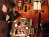
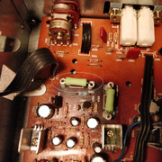
Edit: attached image of resistor in question.
 

Attachments

  • 4096-3072-max.jpg
    4096-3072-max.jpg
    133.4 KB · Views: 39
Last edited:
That resistor is in the power supply section. It’s 5 watts and is designed to get warm, but, of course, it shouldn’t be smoking. You need to unplug the amp and take the bottom plate off, turn the amp on it’s side, with the transformer on the bottom for balance and inspect the solder joints. Start with the resistor, in that area on the solder side, look for “cold solder joints”. If you don’t know what a cold solder joint is, just google it. Where there are signs of heat ( darker brown areas)
 
I tested with an RCA adapter and my phone into the 'main in' and it still only plays out of one channel so it seems to be an issue with the main amp.
EDIT: misread first time, ok, yep appears to be a power amp issue.
Maybe issue with speaker selector, did you try set B also headphones?

I also noticed some smoking coming from a resistor (R905),
Never a good sign, used for +46V regulated supply to power amp front end, Q901 may be suspect. Worthwhile doing basic health
check of power supply voltages (+/-46V, +/-24V and measure R905,906, incircuit ok but amp powered off/unplugged, expect

Some other things to try.
Set "Soft Clipping" switch on rear panel to OFF.
Set "Bridging" switch on rear panel to OFF.
Check for audio at R704 (2.2k), either side, use oscilloscope
10ohms)
 
Last edited:
Little unclear... are you saying there there was no audio at the main-in RCA's, this would point to a preamp issue.
Sorry about that. No I bypassed the preamp and used the phone as a source, going directly into the main in RCA's. There was no sound in the left channel when doing this. Hope this clears it up.
Never a good sign, used for +46V regulated supply to power amp front end, Q901 may be suspect. Worthwhile doing basic health
check of power supply voltages (+/-46V, +/-24V and measure R905,906, incircuit ok but amp powered off/unplugged, expect
10ohms)
Sorry, it was R907 (circled in image), not R905. R905 is the smaller one just beneath it in the picture. Not really sure what to do here to check the health of it. I measured R907 powered off at 230 ohms. Looking at the schematic it seems to be right.(220)
That resistor is in the power supply section. It’s 5 watts and is designed to get warm, but, of course, it shouldn’t be smoking. You need to unplug the amp and take the bottom plate off, turn the amp on it’s side, with the transformer on the bottom for balance and inspect the solder joints. Start with the resistor, in that area on the solder side, look for “cold solder joints”. If you don’t know what a cold solder joint is, just google it. Where there are signs of heat ( darker brown areas)

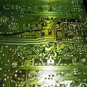
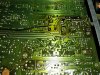
Ok, I did some inspecting of the under-side and it looked ok to me but I'll attach image. I did reflow some of the joints though to be sure.
I noticed also it has a coupple jumped connections on the back, maybe pointing to a previous repair job? I'll have to ask my father as he owned it before me and it hasn't been repaired as long as I've owned it.

Anyways I don't want to plug it in yet as not much really has been done yet. Should I order replacement resistors?

Thanks again both of you. Much appreciated.

Edit: larger res photos:
 

Attachments

  • 40926-3072-max.jpg
    40926-3072-max.jpg
    188.1 KB · Views: 8
Last edited:
EDIT: misread first time, ok, yep appears to be a power amp issue.
Maybe issue with speaker selector, did you try set B also headphones?
I've tried with both speakers and headphones and it doesn't seem to matter which.

Some other things to try.
Set "Soft Clipping" switch on rear panel to OFF.
Set "Bridging" switch on rear panel to OFF.
Check for audio at R704 (2.2k), either side, use oscilloscope
10ohms)
Ok. Is it safe to test do you think, considering the smoking resistor?

Edit: The settings at the back are both OFF. Will test R704 if safe.
 
Last edited:
R907, 220 ohms, used in 24V regulated supply. With amp powered off/unplugged measure resistance of R907, in circuit is
ok, it may have drifter high. Do you have a DBT?
 
R907, 220 ohms, used in 24V regulated supply. With amp powered off/unplugged measure resistance of R907, in circuit is
ok, it may have drifter high. Do you have a DBT?

I measured it at 230 with the amp turned off. Dim bulb tester? No, I do not.
 
Are power supply caps original? eg, C917, C919,,, I'm thinking of isolating the +24V supply and see if R907 settles
down. How soon after power up does it start smoking...
 
Are power supply caps original? eg, C917, C919,,, I'm thinking of isolating the +24V supply and see if R907 settles
down. How soon after power up does it start smoking...
Yes, everything should be original.

It starts smoking pretty immediate. Maybe 1 minute tops.
 
Best to build a DBT, numerous plans on AK, not worth the risk of smoking one of the better NADs. Need to get the amp stable
so as to see what's drawing the extra current, might be a leaky cap or suspect volt reg IC902. Preamp opamp should be ok
since one channel is working. After building DBT, power up on DBT with 40-60W bulb, check R907 is ok. If ok measure DC voltage
to ground at R907 and jumper link(red crosses) Expect about 18-24Vdc at jumper, if significantly lower then lift one leg of
jumper(blue cross) then DBT power up and recheck voltage at jumper.Need to sign off...

upload_2020-9-10_19-9-18.png
 
Best to build a DBT, numerous plans on AK, not worth the risk of smoking one of the better NADs. Need to get the amp stable
so as to see what's drawing the extra current, might be a leaky cap or suspect volt reg IC902. Preamp opamp should be ok
since one channel is working. After building DBT, power up on DBT with 40-60W bulb, check R907 is ok. If ok measure DC voltage
to ground at R907 and jumper link(red crosses) Expect about 18-24Vdc at jumper, if significantly lower then lift one leg of
jumper(blue cross) then DBT power up and recheck voltage at jumper.Need to sign off...

View attachment 1976626

Allright, I made a DBT and tested. Measured voltage to ground at R907 to 23V. Then jumped it to the red cross and then measured at the red cross at 23V again.

No smoking now, bulb is dim and music sounded distant.
 
Last edited:
I made a DBT and tested. Measured voltage to ground at R907 to 23V. Then jumped it to the red cross and then measured at the red cross at 23V again.
Measured R907 to GND gave 23V
Measured jumper link (red cross) to GND gave 23V

These points correspond to the input and output of the voltage regulator. The DBT will lower the input voltage but same voltages
on IN/OUT is unexpected. With amp powered off, measure resistance between the 2 points (R907 and jumper) testing for
possible short in the volt regulator(IC902). Consider replacing if you have a spare +24Vdc 1A item.
 
Measured R907 to GND gave 23V
Measured jumper link (red cross) to GND gave 23V

These points correspond to the input and output of the voltage regulator. The DBT will lower the input voltage but same voltages
on IN/OUT is unexpected. With amp powered off, measure resistance between the 2 points (R907 and jumper) testing for
possible short in the volt regulator(IC902). Consider replacing if you have a spare +24Vdc 1A item.

Hm.. I think I misunderstood the first post. I jumped the red crosses, I guess that was not the intention. Anyways, I measured again now and R907 to ground was 24V. The jumper was 22.5V. Not sure how significant it is. Measured resistance with amp off at 10 MegaOhm(??) and rising..

I ordered caps and voltage regulator yesterday, should show up tomorrow so can try and swap the regulator then.
 
Last edited:
I measured again now and R907 to ground was 24V. The jumper was 22.5V. Not sure how significant it is
That looks better, unlikely failed volt regulator but maybe needs a few more volts...

Problem is that R907 smokes off DBT. It's looking like a downstream problem eg, phono ot tone stage (opamp?).
No harm in replacing the voltreg and psu caps. If problem persists the next step would be to work out where the extra
current is going to. You should check for any signs of heat stress like discoloured resistors and faded lettering on
IC and transistors, candidates would be R628 Q604, R503,5, generally have a close look at the phono stage and around
IC601,Q602,4,7. Also check around the mute function, Q606,7.
 
Back
Top Bottom