You are using an out of date browser. It may not display this or other websites correctly.
You should upgrade or use an alternative browser.
You should upgrade or use an alternative browser.
NAD 6240 Cassette display
- Thread starter dobyman
- Start date
Register to hide this ad

Open it up and check for faulty caps for the display (like the orange cap disease common with Nakamichi flouroscan-ish displays). Reviewing tapeheads.net produced similar issues with other flouro display decks and reflows of the solder connections seemed to fix almost all of them. Of course take a multimeter and measure the connections to ensure it's not a broken solder joint. GL
Last edited:


duncan
flâneur in training
There are a few fuses, yes. If those are okay and you have a voltmeter, measure DC voltage across resistor R6. It should be close to 6v. If it's much lower, then it becomes time to download the service manual and figure out why.
Or you might see if you can enjoy it without meters and not worry about it. I like my 6240. It doesn't look impressive maybe, but it sounds very good and gets a lot of use here.
Or you might see if you can enjoy it without meters and not worry about it. I like my 6240. It doesn't look impressive maybe, but it sounds very good and gets a lot of use here.

dobyman
Turntable Addict
Yes that’s the one.Is the fuse marked FU703?
duncan
flâneur in training
I'm not usually a betting chimp, but might put a little money in this case on capacitor C6 being the culprit. If it is, it should be replaced with 100uf/16v instead of the stock 100uf/10v.
... of course, a little time with a multimeter and a schematic is going to get you to the solution more reliably than listening to some rando like me who doesn't even have the thing in front of him to examine.
... of course, a little time with a multimeter and a schematic is going to get you to the solution more reliably than listening to some rando like me who doesn't even have the thing in front of him to examine.

dobyman
Turntable Addict
I'm not usually a betting chimp, but might put a little money in this case on capacitor C6 being the culprit. If it is, it should be replaced with 100uf/16v instead of the stock 100uf/10v.
... of course, a little time with a multimeter and a schematic is going to get you to the solution more reliably than listening to some rando like me who doesn't even have the thing in front of him to examine.
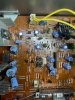
OK, I replaced the fuse just to see what happened and the left meter is working but the right one is not. Mine does not have a R6. (See pic) It should be right next to the C6, but there are no resistors there. I will look at the C6 too, but any ideas why the right meter is not working now?
And bear in mind, I am not a tech, so my knowledge is very limited. Patience please.

duncan
flâneur in training
I guess your deck is from a different production run - on mine, there are two resistors to the left of that white plug with the yellow wires, and one of them is R6. I'd only mentioned it as a convenient place to measure voltage from the top. But I don't think that matters now. The power supply had to be the first suspect when both meters were out, but with one of them working we will want to look elsewhere.
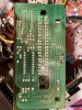
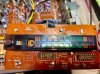
The meter board is attached to the front panel with one screw. Remove that, squeeze a couple of plastic clips and the board should come out easily, still electrically connected by a black 5-wire cable. The issue now is likely to be somewhere on that board. Start by giving it a quick visual examination on both sides - does anything look burned, are any of those little black capacitors domed at the top and/or oozing gunk, do any solder connections look cracked, does anything else jump out at you.
The meter board is attached to the front panel with one screw. Remove that, squeeze a couple of plastic clips and the board should come out easily, still electrically connected by a black 5-wire cable. The issue now is likely to be somewhere on that board. Start by giving it a quick visual examination on both sides - does anything look burned, are any of those little black capacitors domed at the top and/or oozing gunk, do any solder connections look cracked, does anything else jump out at you.

duncan
flâneur in training
Not sure I trust that goop on the top (brown) side of the meter board. It's probably from the factory, and mine has a little of it but not nearly as much as yours; I wonder if it has turned conductive with age. Might be worth using something like a dental pick to break up some of it, especially around where the black cable attaches to the board.
Also sometimes capacitors go bad without being visually obvious. Do you have some way to measure them? If I'm reading the schematic right, the ones to suspect on the meter board for the R channel would be C604 and C606.
Edited to add: removal techniques for glues used in circuit board assembly come up every now and then here. People have different ideas about it....
Also sometimes capacitors go bad without being visually obvious. Do you have some way to measure them? If I'm reading the schematic right, the ones to suspect on the meter board for the R channel would be C604 and C606.
Edited to add: removal techniques for glues used in circuit board assembly come up every now and then here. People have different ideas about it....
Last edited:
dobyman
Turntable Addict
Not sure I trust that goop on the top (brown) side of the meter board. It's probably from the factory, and mine has a little of it but not nearly as much as yours; I wonder if it has turned conductive with age. Might be worth using something like a dental pick to break up some of it, especially around where the black cable attaches to the board.
Also sometimes capacitors go bad without being visually obvious. Do you have some way to measure them? If I'm reading the schematic right, the ones to suspect on the meter board for the R channel would be C604 and C606.
Edited to add: removal techniques for glues used in circuit board assembly come up every now and then here. People have different ideas about it....
I dont know how to check caps, but I can change them, so I might invest a few dollars and recap the meter board. I think I can get them locally anyway. Ill try and pick some of that glue away from the cable too. Thank you! Ill be back.