Hi,
I am having weird issues going on with this receiver. I can solder but have only basic understanding of electronics. Trying to figure out where the problem is. Maybe somebody ran into same issue and could help?
1) Most weird: with power button OFF - I have around 2v of DC offset on speaker terminals (!)
There's a 4700pf capacitor in the power supply unit that I suspect got shorted.
2) When I power the amp on - the DC offset in speaker terminals drops to 50mv and 80mv. Cannot trim it down from that point using the trimming pots.
3) Bias trimming does not do much- but I suspect I am measuring it at wrong points. The manual is not clear on this:
"Connect DC milivoltometer across R150 (output transistor's emitter resistor) and adjust VR102 for 2-4mV reading on meter"
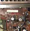
I am attaching the photo of this section of amp PCB board.
Problem is that R150 is the transistor (not resistor). I think that I should be measuring the bias voltage across R145 (right next to "bias" mark)?
Any help would be appreciated. Apologize for dumb/basic questions but I just started my journey with fixing the amps and don't know much yet. (actually started electronics course just for that purpose but I am just a few weeks out. Still got lots to learn! Still lots of fun/frustration ahead of me ;-) ).

I am having weird issues going on with this receiver. I can solder but have only basic understanding of electronics. Trying to figure out where the problem is. Maybe somebody ran into same issue and could help?
1) Most weird: with power button OFF - I have around 2v of DC offset on speaker terminals (!)
There's a 4700pf capacitor in the power supply unit that I suspect got shorted.
2) When I power the amp on - the DC offset in speaker terminals drops to 50mv and 80mv. Cannot trim it down from that point using the trimming pots.
3) Bias trimming does not do much- but I suspect I am measuring it at wrong points. The manual is not clear on this:
"Connect DC milivoltometer across R150 (output transistor's emitter resistor) and adjust VR102 for 2-4mV reading on meter"
I am attaching the photo of this section of amp PCB board.
Problem is that R150 is the transistor (not resistor). I think that I should be measuring the bias voltage across R145 (right next to "bias" mark)?
Any help would be appreciated. Apologize for dumb/basic questions but I just started my journey with fixing the amps and don't know much yet. (actually started electronics course just for that purpose but I am just a few weeks out. Still got lots to learn! Still lots of fun/frustration ahead of me ;-) ).