• The move to the new server is done. There are some software and database maintenance updates in process. This has us passing the hat around to help out. We appreciate any donations. Seriously, even a dollar helps. The payment page may be found here - https://www.audiokarma.org/support.html

NAD 7140 No audio, Preamp problem? New AK'er

tusntuk2

Active Member
Hello, I'm new, this is my first thread, so I hope I do this right. I'm 66, an old musician familiar with tube amps, and I'm working on a NAD 7140 receiver with no sound. I've heard great things about this forum and NAD gear, and I've already followed some suggestions for trouble shooting and repair, but no success yet. The NAD powers up, clicks the relay, and if you listen carefully the faintest signal can be heard in speakers, but no controls work. Yes, amp/preamp connectors are present. The power amp will work with separate input, the preamp output has no signal. The big filter caps (10,000uf) showed lots of brown gunk at the base, so I changed them, but found out it was probably the locking glue instead of leakage. Everything else inside the amp looks clean, with scarcely any heat related damage noticed. Deoxed every control, switch and connection I could, although many switches are difficult to invade. Using the schematic I'm having some trouble measuring voltages, so I'm to the point of needing help. Anybody got any clues or advice? Sure do appreciate it!
 
Register to hide this ad
Greetings and welcome to ak.

I believe you have at least diagnosed it's in the preamp section as the output amp works with separate input. I would PM member "leesonic". He'd know off the top of his head what and where to check which would take others (like me) days to familiarize. Might be worth sending him the unit if he's not too busy.
 
Both channels affected so I'd be leaning towards preamp power supply. Give a few minutes, will try and
get some test points for measurement.
 
The input selector needs to be clean, also an NJM OPAMP is used, maybe melted affecting
both channels. Firstly, the preamp power supply. Please check pin (probably a metal post)
34 (or 17) and 35 (or 16). These should be +/-24Vdc or thereabouts. 34,35 are the preamp
end while 16,17 are the power supply end of the feed.
 
If possible, measure the voltages at the emitter legs of Q604 and 605, this would rule out
downstream components.
 
If possible, measure the voltages at the emitter legs of Q604 and 605, this would rule out
downstream components.
Many thanks for the quick response! I was stumped on the strange readings at 34, 35, that's when I started this thread. 34 is .193 (yes, point 193) and 35 is -4.40. Q604 emitter shows -4.05 and Q605 shows -.176, but might be irrelevant with the other low readings? Selector switch was deoxed again, seems to work, I hear that tiny bleed through of the FM radio through A speakers when switched by the selector position.
 
I would expect voltages at Q604,5 emitters to be about +/-15Vdc so both power rails are affected.
Need to work through the preamp power supply.
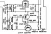
NAD7140psu.JPG

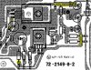
Positive rail, IC902, need to measure IN/OUT voltages, expect OUT to be +0.2 (faulty) or thereabouts
Measure OUT at R922, C918 see pic
Measure IN at C917 or IC leg

Negative rail, Q904, expect OUT to be -4.4 (faulty) or thereabouts.
Measure OUT at R924,5
Measure IN at R920.

Prefer not to measure at TR legs, one slip...
Nad7140art.JPG

You should also measure the resistance of R907 & 908.
In circuit is fine (disconnect all power first)
 
I would expect voltages at Q604,5 emitters to be about +/-15Vdc so both power rails are affected.
Need to work through the preamp power supply.
View attachment 859834

Positive rail, IC902, need to measure IN/OUT voltages, expect OUT to be +0.2 (faulty) or thereabouts
Measure OUT at R922, C918 see pic
Measure IN at C917 or IC leg

Negative rail, Q904, expect OUT to be -4.4 (faulty) or thereabouts.
Measure OUT at R924,5
Measure IN at R920.

Prefer not to measure at TR legs, one slip...
View attachment 859839

You should also measure the resistance of R907 & 908.
In circuit is fine (disconnect all power first)

Great instructions, thanks! OUT for IC902 at R922 is (+ .193) as predicted. IN at C917 is +39.5.
Neg. rail OUT at Q904 is -4.4, as predicted, and IN at R920 is -33.6.
Large heat resistors seem fine, measuring 560 ohms for the 560 ohm #R908, and 467 ohm for the 470 #R907. Ceramic collars are intact, and there is only slight darkening of the PCB board in this area. This is the only darkening on the entire board, but it seems minor compared to some burns I have witnessed. I spy no other apparent heat damage in this area, or in the FM board above.
 
From the measurments both IC902 and Q904 used for voltage regulation have failed. You should check the
solder joints on both, but the suggestion is to replace both.

IC902, a 24V/1A regulator, +39.5V IN which is at the maximum (40V) level.

Suggest MC7824CTG, Mouser 863-MC7824CTG. Must have a heat sink.

Pinout is the same, IN/COMMON/OUT

Q904, 2SB548 maybe something newer, please check. The specs are fairly robust so a little surprised
it failed in this application (-24V/1A).

Suggest Mouser 2N6035 (E/C/B), again heatsink.
My transistor matching is not very good so others welcome to chime in.
 
OK, still looking and learning about replacement for 2N6035. Is there any way to test these parts directly? On the 2N6035 is the pin out different from the 2SB548? And here's a curiosity to me - I had an idea to look for a possible source for the high +39.5v IN for the failed IC, mostly for my own education, so I traced back the line to the transformer. At the Blu/Wht/Blu tap I discovered two 3.3 / 1W resistors (R901,R902) on the schematic that were missing on my PCB. On my board they are simply jumper wires. You can see there are no voltages listed to check, either. The schematic has these labeled as direct replacements, too, so I was curious about that. Any ideas? Underneath it actually does not look like a resolder, but I know you can't tell sometimes. I'll admit my inexperience, of course! I do like to learn and understand it better. I probably know just enough to get myself in trouble...Again, thanks for your help with my new hobby!
 
  • Like
Reactions: mbz
Is there any way to test these parts directly?
IC902, the voltage OUT/IN measurement is 95% it's dead, assuming it's properly soldered in.

2SB548, you can try measuring with a multimeter. avionics has a post somewhere where he walks
you through the various combinations. Will try and find it for you. 2SB548 and 2N6035 have the same
pinout E/C/B, that's confirmed by your voltage measurements.

Again, I must stress that I'm not highly confident about the suitability of 2N6035 as a direct replacement
for 2SB548. Suggest you start another thread specifically asking this question.

At the Blu/Wht/Blu tap I discovered two 3.3 / 1W resistors (R901,R902)

I don't think these are significant. We are only taking about 3.3 ohms. The tolerance on R905,7 and R906,8
would be more than this. At design, someone thought this was a good idea, then they found out they could
save 4 cents. NAD has a bad history in this area (cost cutting).

I do like to learn and understand it better.
Top marks. Question everything and build up your knowledge. NAD are generally very easy to work on and
if you make a mistake...
 
Great stuff. I found a suggested replacement for the 2sb548 at allxref.com as a BD238. I have not tried to digest a spec sheet for a transistor before, so I'm not sure what I'm comparing, but from the looks of it your 2N6035 seems a bit stouter and might disapate more heat. Is that right? More learning. I am enjoying the project and your fine information.
 
Q904,5, R919, 920,1,2,3,5 make up the MAIN components of the -24 power supply.
An operating point on the Q904 data sheets would have been selected that gives
the wanted performance ie, stable Vce for minor variations in mains supply.

As previosly mentioned, my transistor mapping skills are poor. The 2N6035 was
suggested more from a general parameter point of view. Careful analysis of the
datasheets is required so you get the wanted -24V (not -25 or...). I don't have the
skills to do this.

A possible consideration is to replace Q904 with a -24V linear voltage regulator.
M7924CTG is the brother to M7824CTG. This would require disabling Q905 which
would involve minor hacking. M7924CTG would probably provide a more stable
supply, lower noise and better ripple rejection.

Ideas/comments from othe AK members?
 
echowars has suggested KSC2690AY.

Looking at the schematic, R922, 5 form something of a feedback circuit (I think).
The positive supply (+25V) is considered the reference, output from the voltage regulator (M7824CTG).
Any movement in the negative supply, eg -24V will cause a non-zero voltage at the junction of these
two resistors and the base of Q905 causing it to conduct more which in turn affect Q904.
Basically, I think you have some flexibility in the selection of Q904 because of this feedback mechanism.
It's not all doom and gloom as I previously indicated.

Try KSC2690AY.

When you get the power supply sorted, it will need a recap. NAD were notorious for using budget caps.
But that is for another day.
 
echowars has suggested KSC2690AY.
Thanks to EchoWars for the replacement suggestion. I must admit I'm confused, tho. I am not experienced with transistors, (I used to work on tubes), but the KSC2690AY is an NPN and the schematic shows a PNP. The spec sheet for the old 2SB548 says NPN/PNP, although one of these might be 2SB549. I'm trying to learn this stuff, but it can be confusing to me. Can you straighten me out? Thanks!
 
Good pickup, we are getting lazy in our old age, not checking the basics, 2SB.., .KSC...
Go with the compliment of KSC2690AY, use KSA1220AYS.
 
The voltage into IC902 is way to close to the maximum permissible (+39.5/+40V).
Any variation in main voltage will affect. Over time such variation has probably caused
IC902 to fail which then caused Q904 to fail.

When you complete this work and power ON, you should immediately measure
the voltage into IC902. As a precaution you could replace R907 to 560ohms/3W
to burn up some additional volts, however the route cause is probably the current
draw on the positive rail is not correct (not high enough) so the voltage drop across
R907 is not as intended.

Can you measure R628(expect 560ohms)
 
the route cause is probably the current
draw on the positive rail is not correct (not high enough) so the voltage drop across
R907 is not as intended.

Missed the obvious.
Voltage supply to the OPAMP is down so its not drawing its usual 6-8mA.
Replace IC902 and Q904, power up, check voltage into IC902.
Been a long day
 
I'll get the order in Thursday. Do you think I need a "bigger" regulator? I'm thinking "more robust", like if it could handle more input level than 40v. I do not know these things.

R628 was spot on at 556 ohms.

What else affects voltage to IC902? I traced around, checked fusible resistors R905,6 they were fine. I checked +/- 43v rail too, just like the 24v IN/OUT checks, and they were fine. -42.8 to +43.1. That's the power amp side, right? and the power amp was working.

This is getting interesting!
 
Back
Top Bottom