• The move to the new server is done. There are some software and database maintenance updates in process. This has us passing the hat around to help out. We appreciate any donations. Seriously, even a dollar helps. The payment page may be found here - https://www.audiokarma.org/support.html

NAD 7225PE - need a method to isolate TO3 case aka collector from chassis ground

62vauxhall

Addicted Member
Also posted on DIY Audio.

Firstly, I have re-used the mica/thermal paste insulators without success and now have sil pads in place - also without success. So I do not believe that is the issue.

Over the past two years I have picked away at problems with this receiver, including this one, numerous times. During that time, I think I corrected the other shortcomings but this one persists.

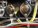
There is continuity between the case of TO3 output transistors and chassis ground when the mounting screws are in place, They are snug but not tight. At the moment, that continuity exists on the two TO3 in the center of the photo. Removing the mounting screws of those two middle transistors eliminates continuity. Even though mounting screws are in place, there is no continuity from either TO3 transistor at each end of the row.

To me the fault would seem to be the plastic insulators used with the TO3's mounting screws. Some of the original insulators were salvageable and some were not. I have tried substitutes including small pieces of shrink tubing (as in the last photo) but so far nothing has worked to eliminate continuity with all of the TO3 output transistors when mounting screws are in place.

I have run out of inspiration so my question is....has anyone here needed to fabricate such an insulator and if so, what did you use?

Or, is there an online source for them and what are they called?

Yes, the trace side is messy and I will clean up the flux if/when I am done unsoldering/re-soldering.

EDIT: I suspect that this short of collector to base is why I cannot adjust idle current on either channel.
 

Attachments

  • IMG_5199.JPG
    IMG_5199.JPG
    139.3 KB · Views: 102
  • IMG_5200.JPG
    IMG_5200.JPG
    173.4 KB · Views: 101
  • IMG_5201.JPG
    IMG_5201.JPG
    53.5 KB · Views: 104
Last edited:
Register to hide this ad
Hopefully this makes some sense.

I once considered those shoulder washers and even think I have some. But there were no such things in place originally. What was in place were short pieces of cylindrical plastic that only prevented the threaded section of the mounting screws from contacting the chassis.

The reason I did not try them is that I envisioned the shoulder, either insulating the mounting screw from the transistor case or preventintg the transistor bottom surface from being flush with the mica or sil pad.

Dependant on if the washer's shoulder is on the top face of the transistor or the bottom face.

The machine screws for the TO3's are what connects their case/collector to the circuit board - the pads at one end of the white jumper wires in my 2nd photo.

But in looking at a TO3 mounting kit, I noticed the solder terminal and I may have some those too. Used in conjunction with a shoulder washer, I should be able to connect the case/collector to where the white jumper wires attach and keep the TO3's isolated from the chassis.
i get where you are coming from. i do not know where to buy those sleeves.
 
Any chance there is a sharp piece of metal on the heatsink that is piercing the sil-pad when you reinstall it?

How about the driver transistors upstream? Q413 and Q414 drive the MJ2955s, although technically they are running off the regulated supply.

What about pulling D509 and D510 and measuring if there is still a short? This would disable the power envelope circuit. Maybe there is a shorted transistor in there?

Lee.

Negative on a sharp piece of metal penetrating the sil pad. I chamfered the holes and they are smooth.

Some time ago, I removed and checked Q413, Q414 plus Q411 & Q412 which were all OK according to a $20 Chinese component tester. I intended on replacing them anyway incase they were "walking wounded" but waited too long. 2SD649A;s became unavailable as did the complimentary 2SD669A's. Or at least I could not find any online at the time.

What I put in their place was KSC2690 and KSA1220 as their compliment - that was done last week.

I located my shoulder washers and solder terminals so will try my idea out tomorrow.
 
Last edited:
The first attempt using those shoulder washers was a fail. Continuity was still present between the cases of the two middle transistors and chassis ground. It was a frustrating outcome.

The only explanation that occurred to me was that somehow the threaded portion of the machine screws were shorting to the insides of the holes they passed through in the heatsink. I discovered that it was just one machine screw each of those two transistors that was shorting.

With nothing to lose, I enlarged the heatsink holes for those two transistors. That seems to have done the trick. The middle transistors are snugged down with their machine screws and the short is gone.

The two transistors at the ends of the row of four, were not problematic so I have left those alone. Shoulder washers and a "case jumper wire" were employed on the two middle transistors only.

I cannot put in much more than one hour per session with this receiver. Especially after dark. I need the natural light to see what I'm doing. Plus the 4' diameter dining table in my former residence where I performed such tasks seems spacious compared with my "work area" now. Sometimes the receiver was in my lap.

Tomorrow I will solder in the two output transistors I've been fiddling with then do a turn on using a DBT. If that does not disappoint, I'll try adjusting the idle which hopefully is now doable.


IMG_5207.JPG

IMG_5207.JPG
 

Attachments

  • IMG_5208.JPG
    IMG_5208.JPG
    150.2 KB · Views: 33
i don't think you have a connection to the collector like that. i didn't fully understand at first but i do now

the insulator washers aren't going to work as long as there is a shoulder on them. i think you are going to have to come up with some type of sleeve. like cutting the washer lip of several insulators and feeding those onto the screws so the screws don't contact the heat sink but the nut contacts the transistor case.

see if @avionic follows what i'm saying and agrees.
 
Yes, I now agree with @painttoad - these probably need sleeves. It seems to me the circuit board is not aligned perfectly with the holes in the heat sink, so the screws are misaligned. The Adcoms I've worked on use sleeves for the outer output transistor screws to locate the entire board; no sleeves are used for the transistors between those. Any misalignment would also short those screws, even with a shoulder washer.
 
Last edited:
I believe you are looking for shoulder washers - nylon, etc. They are pretty much required in cases like this.
Yep. Shoulder washers and TO-3 shaped mica insulators. There is also a silicone rubber based TO-3 shaped insulator that does not need to be used with the silicone grease used with mica types.
 
It seems to me the circuit board is not aligned perfectly with the holes in the heat sink, .

That does seem to be the cause. Last year sometime, I removed the heatsink for whatever reason and it has not been right since. I tried several times to align the holes but was unable to do that perfectly.

I gave up on using sleeves because even with them in place, the case would short to chassis whenever the screw and nut were snugged up.

And I do have the case connected to the appropriate PC pad via a ring terminal on one end of the wire and the solder tab on the other. The solder tab is in face to face contact with the transistor case, the shoulder washer passes through it. The ring terminal on the other end is affixed to the PC board's trace side via the TO3 mounting screw head. So the case and the PC board are connected via the new white wire.

And now a recurring problem....again.

After soldering both TO3's pins, all was good with the DBT. Then I attempted idle current adjustment but with no success.

Idle current on both left and right channels remain unadjustable. Left side is 185mv and right side is 3mv. Turning the pots in either direction does not really do anything.

Any opinions on what might be the cause?

I had very much hoped that eliminating the TO3 case to chassis short would restore idle adjustment.
Check all your power supply values.
 
is the insulator protruding into the transistor mounting hole thru the ring terminal or just thru the ring?

The insulator protrudes through the ring and into the transistor hole. I had to enlarge the hole of the solder terminals for the insulators to do that.

Check all your power supply values.

Yes, I guess so. The thought of a power supply problem crossed my mind as well. Was not looking forward to that as I am not fully adept at reading a schematic.
 
The insulator protrudes through the ring and into the transistor hole. I had to enlarge the hole of the solder terminals for the insulators to do that.


Yes, I guess so. The thought of a power supply problem crossed my mind as well. Was not looking forward to that as I am not fully adept at reading a schematic.
Not to worry, this is just the verification stage. No schematic reading necessary. :)

The voltages you need to find are here:

1692100195102.png

The top 2 voltages (unregulated +/- 30.5 volts) are easily accessed by touching the cans of the output transistors. the 2N3055's should have +30.5 volts between can and ground, the MJ2955's should have -30.5 volts. I'd check each one, since the mounting scheme seems to have the supply wires going to each individual output transistor.

The regulated +30.5 can be found at the wiper of R411, which appears to be the DC offset adjustment. The -28 volts is going to be a little tougher to find or maybe get to. Measure the voltage at either end of R450; the higher voltage should be facing that supply.
 
normally when I see TO-3 mounted like this, the screw head is on the transistor side, sometimes with a star washer, and the hat bushing is on the inside of the heat sink where it is retained by the nut, or going into the TO-3 socket depending on what exactly this uses. There has to be a connection between the screw and whatever the terminal is inside though or you get no collector connection.

The power supply lead going to the collector or emitter may show low resistance to chassis ground through the power supply, so it might be worth just ohm checking that with no transistors connected to confirm. Possible what you are seeing doesn't mean what you think it does.
 
Back
Top Bottom