• The move to the new server is done. There are some software and database maintenance updates in process. This has us passing the hat around to help out. We appreciate any donations. Seriously, even a dollar helps. The payment page may be found here - https://www.audiokarma.org/support.html

NAD 7225PE - need a method to isolate TO3 case aka collector from chassis ground

I really appreciate the suggestions and info. I cannot attend to any of them until later as there are things I must attend to during the day today. Later on, I will pursue what has been said.

A special thanks to Ray Gianelli for the diagram - it should be of immense help.
 
Not to worry, this is just the verification stage. No schematic reading necessary. :)

The voltages you need to find are here:

View attachment 2959046

The top 2 voltages (unregulated +/- 30.5 volts) are easily accessed by touching the cans of the output transistors. the 2N3055's should have +30.5 volts between can and ground, the MJ2955's should have -30.5 volts. I'd check each one, since the mounting scheme seems to have the supply wires going to each individual output transistor.

The regulated +30.5 can be found at the wiper of R411, which appears to be the DC offset adjustment. The -28 volts is going to be a little tougher to find or maybe get to. Measure the voltage at either end of R450; the higher voltage should be facing that supply.

I got as far as measuring the unregulated voltages you pointed out (8 ohm). Instead of +30.5volts and -30.5 volts, I am reading +41 volts and -41 volts.

The other measurements will have to wait until I remove the tuner board. The components I need to access would seem to be underneath it.

EDIT: After removing the tuner board, I was able to obtain the additional voltage readings. They also do not correspond with those on the diagram.

Q511 emitter - 3.3 volts
collector - 5.6 volts
base - 4 volts

C526 negative leg - minus 0.1mv.

It's too late at night to proceed but I am tempted to pull Q511 and test it. I have a new BD139 transistor if Q511 is faulty.
 
Last edited:
I got as far as measuring the unregulated voltages you pointed out (8 ohm). Instead of +30.5volts and -30.5 volts, I am reading +41 volts and -41 volts.

The other measurements will have to wait until I remove the tuner board. The components I need to access would seem to be underneath it.

EDIT: After removing the tuner board, I was able to obtain the additional voltage readings. They also do not correspond with those on the diagram.

Q511 emitter - 3.3 volts
collector - 5.6 volts
base - 4 volts

C526 negative leg - minus 0.1mv.

It's too late at night to proceed but I am tempted to pull Q511 and test it. I have a new BD139 transistor if Q511 is faulty.
While +/-41VDC is more than I would expect, it's unregulated. It's probably OK.

Don't bother pulling Q511; it's most likely fine. The problem lies behind it:

1692176486077.png
By going to the regulator board you've actually gotten yourself closer to the cause of your problem. I put the voltages you measured in red next to Q511. The problem with these voltages are due to the fact that insufficient voltage is being applied to that transistor. You should have +/-50 volts, measured at either the points outlined in blue or green (whichever is easier to find/probe). If you do, the problem is most likely to be found in the yellow box.

Measure the voltage at the emitter of Q508 and see if that's OK.
 

Attachments

  • 1692176260442.png
    1692176260442.png
    49.1 KB · Views: 9
While +/-41VDC is more than I would expect, it's unregulated. It's probably OK.

Don't bother pulling Q511; it's most likely fine. The problem lies behind it:


By going to the regulator board you've actually gotten yourself closer to the cause of your problem. I put the voltages you measured in red next to Q511. The problem with these voltages are due to the fact that insufficient voltage is being applied to that transistor. You should have +/-50 volts, measured at either the points outlined in blue or green (whichever is easier to find/probe). If you do, the problem is most likely to be found in the yellow box.

Measure the voltage at the emitter of Q508 and see if that's OK.

So far, I have checked voltages within the green and blue areas you indicated and they are very close to those on the diagram. Within a plus or minus volt.

My next check was the voltage at emitter of Q508 and it was not even close. The diagram says minus 28 volts and I was reading minus 1.6 volts.

Voltage at base was wrong too at minus 2.2 volts not minus 29,5 volts. But voltage at collector was OK at minus 51 volts.

(Yellow box) I checked voltages of at Q507. Emitter was +5.6 volts as previously noted.
Base was +6.2 volts and collector was +51 volts. Both of those are somewhat close to the voltages on the diagram.

My temptation is to replace Q508. Or is that jumping the gun?

I have yet to look closely at Q509 and the other components within the yellow box.
 
As usual, @mbz is right on the money. The positive portion of the regulator is referenced from the negative supply via the voltage divider formed by R519, R520, R523 and R524. If the negative supply is bad it affects the positive. Q510 looks like a likely suspect.
 
Check R514,6 and Q510.
Odd that both +ve and -ve rails are down, tempted to unload/isolate the power supply to see if it normalizes

I followed your suggestions and R514 and R516 are within spec.

Q510 though has a problem. The pin voltages were incorrect so I pulled it to check with the $25 on Amazon, Made in China multi-component tester that I have. Q510 is a 2SA1015Y PNP which that component tester identified as a diode not a BJT.

1015 sounded familiar so I checked what few PNP transistors I have but there are no 2SA1015Y's. Mouser has KSA1015YTA's in stock so I need to order some. Till then it's hurry up and wait to see if replacement fixes things.
PM sent.
 
My Digikey order arrived this afternoon - 4 days after ordering. This evening I replaced Q510 with one of the KSA1015Y transistors I received Once installed I turned the unit on to see if idle adjustment had been restored. It had not.

Then, to compound things, R452 became burnt and scorched.

I had to walk away.

Not sure yet if I have a correct replacement resistor - I probably do. But what caused it to burn is currently unknown to me. Interpreting the schematic as best I can, is prompting me to check the transistors associated with R452:

Q406, Q408, Q410 and Q412. Plus diode D406.

That will likely be tomorrow when I can think about this more clearly than I can now.

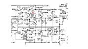
NAD 7225PE schematic area of R452.PNG
 
  • Like
Reactions: mbz
Why is this diagram different from the one above? Did you get the BCE correct on the replacement transistor?
 
Why is this diagram different from the one above? Did you get the BCE correct on the replacement transistor?

The earlier diagram was posted by Ray Gianelli, to illustrate a section where he suspected a failed component was located. I discovered Q510 (2SA1015Y) was defective and replaced it with KSA1015Y.

Pinout is the same for both.

The most recent diagram, posted by myself, illustrates the area surrounding R452 within the main amplifier which burned right after installing the new KSA1015Y at position Q510,
 
maybe I'm blind here but I don't see Q510 on that bit of schematic? Unless you mean Q410

No, not blind. Q510 is not within the diagram section I attached. Q510 is in this, a previous diagram section provided by Ray Gianelli.

It is a different section of the main board from where burnt R452 is located.

NAD 7225PE 2nd diagram from AK Ray Gianelli.png
 
Ah, ok, gotcha, unrelated section of the unit entirely, assuming the power supply voltages are now where they belong after replacing that part

assuming the supply is right, R452 would only cook from excess current flow, thinking shorted Q412 most likely, especially if the output transistors are what originally failed and started this whole thing. I've had outputs short and take out the stage before them more than once, and sometimes it goes back a little further. This is one of the things I find annoying about solid state amps, its like trying to re-stack dominos.
 
My Digikey order arrived this afternoon - 4 days after ordering. This evening I replaced Q510 with one of the KSA1015Y transistors I received Once installed I turned the unit on to see if idle adjustment had been restored. It had not.

Then, to compound things, R452 became burnt and scorched.

I had to walk away.

Not sure yet if I have a correct replacement resistor - I probably do. But what caused it to burn is currently unknown to me. Interpreting the schematic as best I can, is prompting me to check the transistors associated with R452:

Q406, Q408, Q410 and Q412. Plus diode D406.

That will likely be tomorrow when I can think about this more clearly than I can now.

View attachment 2965222
Q410 is your bias transistor (the dotted outline indicates it's mounted on the heat sink with the outputs). Don't try to fire it up again without a dim bulb tester.

Something may still be wrong in the power supply, or one channel of the amp.
 
My Digikey order arrived this afternoon - 4 days after ordering. This evening I replaced Q510 with one of the KSA1015Y transistors I received Once installed I turned the unit on to see if idle adjustment had been restored. It had not.

Then, to compound things, R452 became burnt and scorched.

I had to walk away.

Not sure yet if I have a correct replacement resistor - I probably do. But what caused it to burn is currently unknown to me. Interpreting the schematic as best I can, is prompting me to check the transistors associated with R452:

Q406, Q408, Q410 and Q412. Plus diode D406.

That will likely be tomorrow when I can think about this more clearly than I can now.

View attachment 2965222
Did you verify your voltages from the power supply after replacing Q510?
 
Not yet. It's 3AM here and I should not have woken up so early but I did. Consequently, I've been looking at the schematic and plan to check for the +41 volts that's supposed to be present at R456.

I may still try for a couple more hours sleep.

The only thing I did do last night was measure voltage on both sides of the scorched resistor, R452. It surprised me that it still measured 33 ohms.

The resistors leg in contact with the base of Q412 and collector of Q410 read minus 12 volts. Reading on the other leg, going to Q408 emitter was minus 6 volts. So R452, a 1/4 watt 33 ohm resistor dropped negative voltage by 6 volts?
 
6v across 33 ohms is 181 ma, and it would have been dissipating a full watt. 1/4w part wouldn't have liked that very much but it would do it for a while. Carbon film resistors will cook along grossly beyond rated dissipation for longer than you might think.
 
Back
Top Bottom