• The move to the new server is done. There are some software and database maintenance updates in process. This has us passing the hat around to help out. We appreciate any donations. Seriously, even a dollar helps. The payment page may be found here - https://www.audiokarma.org/support.html

NAD C 370 Protection Mode Issue

leray1

AK Subscriber
Subscriber
I bought a NAD C 370 for cheap but I believe it suffers from the infamous Protection Mode issue. At power up it goes to Relay (orange), then Normal Operation (green) but after a few seconds it goes to Protection (red).

Nothing looks "toasty" on the circuit, could it be something else?

If it is, to get the protection circuit out, do you just pull up on it or is there something else I need to do, like go at it from underneath?
 
Register to hide this ad
Im not familiar with what the specific fault with this unit could be but would suggest once the unit is in green mode - measure the DC offset at the speaker terminals with a DMM meter set to DC mV
 
Cause could be a failed component normally in the power amp stage or in the protection circuit.
As mentioned above, you will need to take voltage measurements to track it down. Are you comfortable
working on a live unit/lethal voltages inside.
 
Cause could be a failed component normally in the power amp stage or in the protection circuit.
As mentioned above, you will need to take voltage measurements to track it down. Are you comfortable
working on a live unit/lethal voltages inside.

I'll probably change out the few capacitors on the protection circuit that get dried out from heat and minimize the heat as best I can with hacks I've read about. If that doesn't correct it I'll look into tracing the problem with voltage measurements. I've researched it but never actually done it. The few repairs I've done have ended up being good guesses and I'm hoping this one will turn out the same.
 
I see you also have KEF 104/2's - very nice speakers! Im refurbing mine currently.

You cant get much easier than taking DC offset readings for your NAD as a first step.
 
  • Like
Reactions: mbz
You cant get much easier than taking DC offset readings for your NAD as a first step.
Yeah, I would have to agree. While replacing caps on a NAD is "never" a bad idea a better approach would be some simple voltage measurements
to identify the problem. Will try and get some test points for you but the measurements at the spkr posts(slimecity) while Normal operation (LED green) may indicate
a climbing DC offset and a good start.
 
I checked DC offset and it was unstable while in protection, but it went out of Protection to Normal (green) after a minute or so. In Normal, the DC offset was ~17mV on the left and ~28mV on the right. I can smell it heating up (it's kind of dusty inside).

More reading to do...
 
I checked DC offset and it was unstable while in protection, but it went out of Protection to Normal (green) after a minute or so. In Normal, the DC offset was ~17mV on the left and ~28mV on the right. I can smell it heating up (it's kind of dusty inside).
OK - so this would appear to be in range - we know its not a DC offset issue.

Next step would be mbz's test point voltages which I bet he will post soon!
 
Apology for the delay, my day job got in the way...

The amp uses uPC1237HA as the protection chip. Apart from dc offset
there is p-on/off mute and over current.

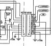
There is a connector on the protection board that has voltages of interest.
If you can measure the voltages at pins 1->10 after the amp goes in protect.
Measure on either the protect board or the other end, not sure if this is
possible/difficult, looks like a cut cable, maybe post a pic if having
difficulties. Probably need to attach a pin to the end of the probe...

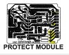
NAD_protect_1.JPG
NAD_protect_2.JPG
Probe.JPG
 
I tried to measure voltages but it's tight and I ended up shorting two components with my probe, causing a spark and a little smoke. I will just replace the capacitors on the protection module, move the diode to the other side and see what happens. Hopefully I didn't destroy anything with my probe, but now it seems to not want to come out of protection mode.
 
We need to work out what was damaged by the short and also whats
going on, ie, amp doesn't come out of protection.

Below DC Voltage measurements are on the protect board, measure at the points
highlighted.

Pin 1, overload, 9mV, measure at R776(22k) end closest to connector
Pin 2, DC-offset, Left, xxmV, measure at R774(56k) end closest to connector
Pin 3, DC-offset, Right, xxmV, measure at R773(56k) end closest to connector
Pin 4, AC detection (P-on/off), Measure AC voltage at R787(10k) end closest to connector
Pin 5, Ground, skip for time being
Pin 6, Protect/Mute signal, measure at R790(10k), end closest to R776
(measure other end of R790, needed for pin 9)
Pin 7, Relay drive, 24.2Vdc,
Pin 8, measure at R780(10k), end closest to R790
Pin 9, Voltage supply+V34R=42Vdc, measure at R790(10k), end furtherest away from R776
Pin 10, leave for time being


If it's difficult to measure at these points then don't risk it, will find other locations.
 
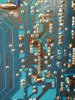
I think what I did is correct. The 10 solder joints in the photo are the ones for the protect module. I put one probe on the joint and the other on the chassis. These are my measurements starting from the bottom:
1. 11mv
2. -1.7mV to -2.9mV (drifts up and down)
3. -35.6mV drifts down to around -11mv and then immediately back to the -35mv and drifts back down, repeats
4. 2.5 to 7.5mV drifts up and down
5. 4.6mV
6. 22.82V
7. drifted from 127mV to about 211mV and back down (slowly)
8. 11.9V
9. 44.6V
10. 3.413V

20180424_072016_resized_1.jpg
 
  • Like
Reactions: mbz
Pins 6&7 are the standouts, also pin 4 doesn't align with sm.
Will try and work out next step but a little busy...
 
Back
Top Bottom