• The move to the new server is done. There are some software and database maintenance updates in process. This has us passing the hat around to help out. We appreciate any donations. Seriously, even a dollar helps. The payment page may be found here - https://www.audiokarma.org/support.html

NAD C 370 Protection Mode Issue

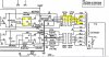
Looking at connector M702, the inputs, pins 1,2,3 (over I, L&R dc) are insufficient to trigger protection.
Pin 6 is high, triggering the mute/protect function. Pin 7, relay drive is low/relay not activated.
Need to workout how this fits in with the damaged part from the short, might be a failed transistor.
 
M704 pin 4 is an AC voltage, the uPC uses the AC to detect p-off/on and performes the necessary
muting. I'm thinking the uPC does not see mains AC so does not activate the relay

Measure M704 pin 4 on the AC scale, should be about 35Vac.
With amp unplugged diode test D720, in circuit is ok. Expect about 600mV and OL in other direction
Measure resistance R787 (10k), in circuit ok
Visually check C783 then measure resistance between D720 cathode and chassis, it should climb
corresponding to charging up C783.
 
Pin 4 AC started at about 0.770V and climbed to 0.813 and fluctuated +/- 0.004 or so. Going back after typing that it was in the 0.250 range and steadily dropping.

The diode is difficult to get to, but I think I had good contact. I had less than 200mV and it was dropping, swapping leads made it go negative and climb.

R787 is good

I can't get to C783 but I plan on replacing all of the capacitors on the protect circuit anyway. If you need that measurement I could try to remove the board from the chassis to access it.

No rush on a response, I'll have limited time this evening.
 
I'm having problems with M704 pin 4. SM suggests that it should be about 35Vac.
The uPC datasheet says at least 0.6Vac is needed. One possibility is that something (C783?, the uPC) is dragging
the voltage down. Other possibility is a transformer issue.
 
The following is to confirm the AC supply is ok, needed by the uPC.
Choice of,
either,
- Measure AC voltage between Grey and Orange transformer wires
- Measure AC voltage at rectifier B703, use clips
- Measure DC voltage at retifier output +, -, use clips

whatever is easiest
C370ac.JPG

B703.JPG
 
- Measure AC voltage between Grey and Orange transformer wires = 76.6V
OK, that's good news, there is AC, although a bit higher than expected, means that transformer winding is ok.

So back to pin 4 of the uPC chip. It detects the AC(power ON) then activates the mute timer (4-8seconds?) then activates the speaker relay
provided there is no excessive dc. If the uPC does not see AC then no relay. Data sheet had 0.6Vac required. Think you need to go back to
connector MZ702 (or other end M702) and look where you can test pin 4 of that connector, measure AC, black probe on chassis. Don't take risks, don't
need a short. From the schematic the path is R787 and D720 then uPC pin 4 so testing anywhere on this part would be ok, maybe use a clip.

Did you replace C783? 4.7uf/50V
 
I measured 4.59Vac on pin 4 where it connects to the top of the board. Is that what you meant by "other end M702"?

I haven't replaced anything on this, yet.
 
I measured 4.59Vac on pin 4 where it connects to the top of the board. Is that what you meant by "other end M702"?
yeah, I wanted the other end of the cagle, guessing it was called M702. AC is present, that's good, but should be around 35Vac. Still looks like something
is dragging the voltage down, it would be good to confirm this by measuring AC at D720 cathode, but this is difficult to get to. Suggest replace C783 4.7uf/50V
 
Sorry for the delay, I've been researching parts. I decided to go with a cap kit, https://sparedparts.com/products/75979476, for the protection circuit. I overpaid but i was having a hell of a time finding these individually on Mouser or Digikey.

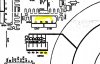
Now I need to know the easiest way to get at the circuit. Do I remove the protection circuit from the main board or just remove the main board?
 
My humble thanks to those who contributed to this thread - it's still doing good, 8 years later. I was given a C370 with the protection problem. Recapping the protection board fixed the issue. :bowdown::bowdown::bowdown:
 
I know this is an old thread but I'd like to add something.
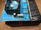
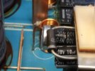
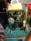
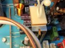
The protection board on the one I just worked on had bad caps, one with high ESR. I replaced them then put the diode on the other side of the board to keep the heat off the new caps. Moved the four wires to the right of the board to keep them off the diode.

This one had a problem where one channel wouldn't come in until the unit was tapped on top. I checked for cold solder joints on the speaker jacks but they were good. Reflowed them anyways.

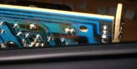
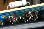
Next I pulled the amplifier for the suspect channel to look it's solder joints over. These amplifier boards have a large three watt resistor at each end of the board which get very hot. Found they were desoldering themselves from the board so I removed the old solder and put new solder on all four of the resistors on both boards.

Just something that should be checked.

IMG_20260126_034914091.jpg

IMG_20260126_035125679.jpg

IMG_20260126_041838076 (1).jpg
 
Last edited:
I don't own a c370 but did fix my c270 with fresh caps (the power amp of the c370). Always good to check solder joints.

I've seen high ESR caps even on a 1uF electrolytic that has affected the protection circuit. I used a cheap component tester to measure the cap.
 
I don't own a c370 but did fix my c270 with fresh caps (the power amp of the c370). Always good to check solder joints.

I've seen high ESR caps even on a 1uF electrolytic that has affected the protection circuit. I used a cheap component tester to measure the cap.
The protection on the one above someone put a 100µf cap in place of the 47µf. The 10µf cap read 40Ω.

Notice how much the heat shrunk the cap's plastic cover. Moving the diode will help a lot.

IMG_20260125_133908381.jpg

IMG_20260125_132636159.jpg

IMG_20260125_141734557.jpg
 
Back
Top Bottom