Well, not sure if you would believe me, maybe I'm simply deluded. A problem with the NAD C326BEE amplifier. The sound - flawless, but the heatsink is too hot - about 70 C. One of the channels has too high quiescent current. Normal for a while on power-up, then after about a minute rises sharply, regardless of whether the amp is cold or hot (I mean if it runs for an hour, quick off-on, you would observe the same sequence; funny thing - if you do so (off/on) you may feel the heatsink cooling down to pleasent warmth, then suddenly all over again). The correct current should be in the range 30-35 mA. It goes up to about 600 mA. Half an ampere works very much like a part of central heating. Bias = 0, no visible / measurable / audible damage. Only this current out of range... Can anyone help me understand what I'm dealing with?


You are using an out of date browser. It may not display this or other websites correctly.
You should upgrade or use an alternative browser.
You should upgrade or use an alternative browser.
NAD Idling Current C326BEE
- Thread starter Darek1048
- Start date
Register to hide this ad

Binkman
Lunatic Member
Welcome to A.K.!
I don't have any exp. with this amp. However any history may be of use.. when did this symptom show up?
Manuals here : https://www.hifiengine.com/manual_library/nad/c326bee.shtml
(I post up manuals for readers, too)
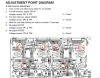
what meter readings do you get per adjustments per TP test points?
I don't have any exp. with this amp. However any history may be of use.. when did this symptom show up?
Manuals here : https://www.hifiengine.com/manual_library/nad/c326bee.shtml
(I post up manuals for readers, too)
what meter readings do you get per adjustments per TP test points?

jhjove
Well-Known Member
I just restored a NAD C325BEE in February.
From the images I searched for on the C326BEE both seem to share same floor-plan and form factors.
My C325BEE was an "ebay special" with some hackery evident. Short story, I replaced every e-cap, several were acting as resistors.
NAD used JH + Jamicon brands rated @85C and some voltage ratings had very little head room.
Also paid special attention to the "riser" PCBs that drive the main amp.
Of course being a NAD; solder reflows on the high thermal areas is a must.
From the images I searched for on the C326BEE both seem to share same floor-plan and form factors.
My C325BEE was an "ebay special" with some hackery evident. Short story, I replaced every e-cap, several were acting as resistors.
NAD used JH + Jamicon brands rated @85C and some voltage ratings had very little head room.
Also paid special attention to the "riser" PCBs that drive the main amp.
Of course being a NAD; solder reflows on the high thermal areas is a must.
Welcome to A.K.!
I don't have any exp. with this amp. However any history may be of use.. when did this symptom show up?
Manuals here : https://www.hifiengine.com/manual_library/nad/c326bee.shtml
(I post up manuals for readers, too)
what meter readings do you get per adjustments per TP test points?
View attachment 2193535
Well it is 8 y. old amplifier. Never opened before. A bit dusty inside - it was always 'hottish', but recently simply switched off - apparently of overheating. Cleaned, air-dusted, refreshed looks alright, and at that stage I decided to check and adjust idling current. One channel 3.5 mV, the other proved troublesome.
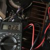
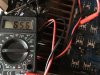
Test Points as indicated in service manual. TP 3 - 4 => 3.5 mV - as adjusted, TP 1 - 2 => floating. After power on value around 2 mV, then after some time (most likely 15 - 20 sec, but could be a couple of minutes, long enough to cool down the heatsink) it rises up to something around 45 - 70 mV, which translates to more than 0.5 A idle current.
What I did so far - referring to Manual and symbols from PCB:
Checked plenty of voltages finding no deviation, including Bias at perfect 0V. Swapped Q160 / Q360 - temperature sensing transistors attached to heatsink, and their wirings - no change. Since no obvious damages / burns are visible and no audio distortion detectable (please believe me, I would hear failing power amp) - just this temperature / current issue, I start to consider whole power transistors replacement. Perhaps with matched Toshiba pairs instead.
+++
BTW regarding "being a NAD; solder reflows on the high thermal areas is a must" is probably very true, but we must remember their PCBs are surprisingly prone to soldering. So easy to destroy it. I would definitely do it, if I could find any suspicious soldering. But please remember, the higher current sets at stable value, however high, still allowing my NAD to operate. Heatsink reaches 70 C, but cut-off temperature is still 10 degrees higher.


Alameda_crag
New Member
Just wondering if you ever managed to fix this problem? I'm having the exact same issue with my 326BEE, i'ts overheating and shutting off. Checked the TP points and R channel is well above spec around 60-70mA and producing a significant amount of heat. Only started happening a few days ago after around 7 weeks of no use. Any help would be great, thank you.

xykapec
New Member
Registered just because of this post.
Don't know if you solved the issue. If you did, then please share how you did it.
Thanks
I had similar problem where I could not set the idle current - it was drifting too fast to not clear direction (sometime higher , sometimes lower) and finally the amp (c326bee) got to state where I could not set the current lower then 4.5mV on both channels (when max is 3.5 in service manual).
So I decided to replace original trimpots with new (better version)
BOURNS - 3296Y-1-201LF - TRIMMER, 25 TURN 200R
And replacement went well.
And for the first time after replacement I even managed to configure the idle currents to 3.1mV on both channels.
But after couple of hours of listening on average volume the sound went bad again.
I measured resistors that are installed in series with trimpots R432 and R232 and they had OK value (slightly above 500ohm, as per spec).
Also both R233 and R433 are fine.
Then I I replaced both transistor Q348 and capacitor c417 (on one channel first).
But this change did absolutely no effect.
Then I replaced all C160, C161, C162, C163, C360, C361, C362, C363 capacitors (as they could leak, giving higher idle current then needed).
All are from Nichicon UKA and UKZ.
Original capacitors were relatively good in terms of ESR and capacitance. So they were perfectly fine and this replacement gave no effect too!
Then I talked to one guy, who has a lot of experience in audio gear. He said that usually when problem is around floating uncontrollable currents one should look to direction of bad tired semiconductor elements.
So I measured (on main board) resistances on Zener diodes D322, D323, D122, D123 and saw some really noticeable differences between them (with respect to their direction in circuit!).
I replaced these 4 Zener diodes (MMSZ5231BT1) and after that I have control on idle current (voltages)!
Sound improved! Before that it was kinda dead, lifeless.
I gave to amp to run for some 4-6 hours, repeating idle currents setting procedure from service manual.
Currents were drifting away each time, but now they are on 3.1 mV on both channels stable.
But I will check them again after some days, then after some weeks (usually it its iterative process till everything will be stabilized completely).
So I suggest you to replace these diodes too (they are very accessible on the board, so it is not very hard job for someone who has experience with soldering iron).
BUT
Another problem that I have with the amp is below (it existed from the beginning, before all replacements above that I completed).
The amp has huge heat sink with 4 main transistors on it (2 per channel).
Besides that it has 8 additional small heat sinks (4 per channel) with small transistor on each of them.
When amp is working the main heat sink is hardly warm,
4 of small heat sinks (2 from one channel and 2 from another channel) are warm ,
4 of small heat sinks (2 from one channel and 2 from another channel) are very very hot.
From now lets talk about one of channels (same heating issue on both channels). Look at scheme in service manual.
Cold small transistors are Q346, Q350.
Very hot small transistors are Q342, Q344.
Do you guys have same problem in your c326bee?
My thoughts on a problem.
What causes heating of transistors? High current that flows through them, right?
What dictates the current value through Q342, Q344?
As I understand diodes D324, D325, D326, D327 are responsible for value of current that flows through Q342, Q344.
Probably these diodes became very tired and they allow higher current to flow through Q342, Q344.
So, as a start I want to replace these diodes.
Am I going in correct direction? What else can cause such heating? Maybe transistors themselves got tired?
Anything else?
Isn't it strange that big heat sink stays cold? Looks like amp is working mostly on small transistors..
Don't know if you solved the issue. If you did, then please share how you did it.
Thanks
I had similar problem where I could not set the idle current - it was drifting too fast to not clear direction (sometime higher , sometimes lower) and finally the amp (c326bee) got to state where I could not set the current lower then 4.5mV on both channels (when max is 3.5 in service manual).
So I decided to replace original trimpots with new (better version)
BOURNS - 3296Y-1-201LF - TRIMMER, 25 TURN 200R
And replacement went well.
And for the first time after replacement I even managed to configure the idle currents to 3.1mV on both channels.
But after couple of hours of listening on average volume the sound went bad again.
I measured resistors that are installed in series with trimpots R432 and R232 and they had OK value (slightly above 500ohm, as per spec).
Also both R233 and R433 are fine.
Then I I replaced both transistor Q348 and capacitor c417 (on one channel first).
But this change did absolutely no effect.
Then I replaced all C160, C161, C162, C163, C360, C361, C362, C363 capacitors (as they could leak, giving higher idle current then needed).
All are from Nichicon UKA and UKZ.
Original capacitors were relatively good in terms of ESR and capacitance. So they were perfectly fine and this replacement gave no effect too!
Then I talked to one guy, who has a lot of experience in audio gear. He said that usually when problem is around floating uncontrollable currents one should look to direction of bad tired semiconductor elements.
So I measured (on main board) resistances on Zener diodes D322, D323, D122, D123 and saw some really noticeable differences between them (with respect to their direction in circuit!).
I replaced these 4 Zener diodes (MMSZ5231BT1) and after that I have control on idle current (voltages)!
Sound improved! Before that it was kinda dead, lifeless.
I gave to amp to run for some 4-6 hours, repeating idle currents setting procedure from service manual.
Currents were drifting away each time, but now they are on 3.1 mV on both channels stable.
But I will check them again after some days, then after some weeks (usually it its iterative process till everything will be stabilized completely).
So I suggest you to replace these diodes too (they are very accessible on the board, so it is not very hard job for someone who has experience with soldering iron).
BUT
Another problem that I have with the amp is below (it existed from the beginning, before all replacements above that I completed).
The amp has huge heat sink with 4 main transistors on it (2 per channel).
Besides that it has 8 additional small heat sinks (4 per channel) with small transistor on each of them.
When amp is working the main heat sink is hardly warm,
4 of small heat sinks (2 from one channel and 2 from another channel) are warm ,
4 of small heat sinks (2 from one channel and 2 from another channel) are very very hot.
From now lets talk about one of channels (same heating issue on both channels). Look at scheme in service manual.
Cold small transistors are Q346, Q350.
Very hot small transistors are Q342, Q344.
Do you guys have same problem in your c326bee?
My thoughts on a problem.
What causes heating of transistors? High current that flows through them, right?
What dictates the current value through Q342, Q344?
As I understand diodes D324, D325, D326, D327 are responsible for value of current that flows through Q342, Q344.
Probably these diodes became very tired and they allow higher current to flow through Q342, Q344.
So, as a start I want to replace these diodes.
Am I going in correct direction? What else can cause such heating? Maybe transistors themselves got tired?
Anything else?
Isn't it strange that big heat sink stays cold? Looks like amp is working mostly on small transistors..
Last edited:
jhjove
Well-Known Member
Very hot small transistors are Q342, Q344.
My thoughts on a problem.
What causes heating of transistors? High current that flows through them, right?
What dictates the current value through Q342, Q344?
As I understand diodes D324, D325, D326, D327 are responsible for value of current that flows through Q342, Q344.
Probably these diodes became very tired and they allow higher current to flow through Q342, Q344.
So, as a start I want to replace these diodes.
Am I going in correct direction? What else can cause such heating? Maybe transistors themselves got tired?
Anything else?
Isn't it strange that big heat sink stays cold? Looks like amp is working mostly on small transistors..
Have you done any comparison voltage measurements; left vs right channel?
How about the 15 ohm resistors (R435, R441 | R235, R241) how do these measure (ohmic value, voltage drop) and compare channel to channel?
I'd check the flameproof resistors too: R406, R410 | R206, R210), if they drifted their changes could affect the other devices in the circuit.
I would think the big heatsink should be cool, unless you drive the amp hard, at this point there would be certainly more current flow through
the big output devices.
Overall, you have fixed the amp (bias is under control and in spec)......what is the DC output measuring? Have you adjusted the ISC circuit?
xykapec
New Member
Hi. Thanks for your reply!
I checked ohmic resistance of R435, R441 | R235, R241 without taking them of the board.
All measured 15.2-15.5 ohm, which is expected values as I think.
I don't want to measure voltage drops when unit is turned on. Last time I tried I burned R441
I get 0.65V voltage drop on R441 (before I burned it), this means that through Q342 I have current of 43mA.
In comparison to Q350 (transistors that don't get hot) - there I have 35mA (the idle current).
As for these resistors I think they are OK - all of them measure from 98.5 ohm to 100.2 ohm.
I did not measure that DC output, but I think its OK there (measured about year ago or so).
I did not adjust the ISC circuit, I don't have the oscilloscope for this.
But I plan to do it in the future with replacing trimpots around this mechanism to better once from Bourns.
I already did such replacement for trimpots that control idle currents tuning.
I checked the spec of these diodes that control the small transistors:
D124, D125, D126, D127
D324, D325, D326, D327
They are specified in service manual as "SMD DIODE LL4148 SOD80 (VISHAY)".
I bought 20 pieces of "LL4148 - SMD-Si-Diode 100V 150mA Minimelf" for possible replacement.
The spec of them is here:
https://www.vishay.com/docs/85557/ll4148.pdf
It says there for forward current F = 5 mA (our case as I understand) it should give forward voltage from 0.620 to 0.720.
I turned the unit on and run it for some 5 minutes then measured voltage drop on all pairs:
D324-D325: 1.025V
D326-D327: 1.250V
D124-D125: 1.243V
D126-D127: 1.248V
But on diode pairs from same model that stand aside from amp section (far from heat area) I see:
D320-D321: 1.295V
D120-D121: 1.305V
From this I conclude that at least one pair of diodes is not OK: D324-D325: 1.025V.
I measured voltage on both:
D324: 0.625V
D325: 0.390V
So the bad diode here (as I think) it is D325.
The rest of diodes are working on their minimum voltage values.
Question: can I say that as time of use passes the diode forward voltage tend to decrease?
Is this correct statement?
For now I will replace the D325 and will see what will happen.
But maybe other diodes need the replacement too.
Ok, we see that D325 is not OK and it possibly explains why we have extra heating of Q142, Q144 on one channel.
But what with hot Q342, Q344 on other channel? What is the source of their extra heating? Will see.
How about the 15 ohm resistors (R435, R441 | R235, R241) how do these measure (ohmic value, voltage drop) and compare channel to channel?
I checked ohmic resistance of R435, R441 | R235, R241 without taking them of the board.
All measured 15.2-15.5 ohm, which is expected values as I think.
I don't want to measure voltage drops when unit is turned on. Last time I tried I burned R441
I get 0.65V voltage drop on R441 (before I burned it), this means that through Q342 I have current of 43mA.
In comparison to Q350 (transistors that don't get hot) - there I have 35mA (the idle current).
I'd check the flameproof resistors too: R406, R410 | R206, R210), if they drifted their changes could affect the other devices in the circuit.
As for these resistors I think they are OK - all of them measure from 98.5 ohm to 100.2 ohm.
Overall, you have fixed the amp (bias is under control and in spec)......what is the DC output measuring? Have you adjusted the ISC circuit?
I did not measure that DC output, but I think its OK there (measured about year ago or so).
I did not adjust the ISC circuit, I don't have the oscilloscope for this.
But I plan to do it in the future with replacing trimpots around this mechanism to better once from Bourns.
I already did such replacement for trimpots that control idle currents tuning.
I checked the spec of these diodes that control the small transistors:
D124, D125, D126, D127
D324, D325, D326, D327
They are specified in service manual as "SMD DIODE LL4148 SOD80 (VISHAY)".
I bought 20 pieces of "LL4148 - SMD-Si-Diode 100V 150mA Minimelf" for possible replacement.
The spec of them is here:
https://www.vishay.com/docs/85557/ll4148.pdf
It says there for forward current F = 5 mA (our case as I understand) it should give forward voltage from 0.620 to 0.720.
I turned the unit on and run it for some 5 minutes then measured voltage drop on all pairs:
D324-D325: 1.025V
D326-D327: 1.250V
D124-D125: 1.243V
D126-D127: 1.248V
But on diode pairs from same model that stand aside from amp section (far from heat area) I see:
D320-D321: 1.295V
D120-D121: 1.305V
From this I conclude that at least one pair of diodes is not OK: D324-D325: 1.025V.
I measured voltage on both:
D324: 0.625V
D325: 0.390V
So the bad diode here (as I think) it is D325.
The rest of diodes are working on their minimum voltage values.
Question: can I say that as time of use passes the diode forward voltage tend to decrease?
Is this correct statement?
For now I will replace the D325 and will see what will happen.
But maybe other diodes need the replacement too.
Ok, we see that D325 is not OK and it possibly explains why we have extra heating of Q142, Q144 on one channel.
But what with hot Q342, Q344 on other channel? What is the source of their extra heating? Will see.
jhjove
Well-Known Member
These are measured with probes: black - cathode, red - anode?I turned the unit on and run it for some 5 minutes then measured voltage drop on all pairs:
D324-D325: 1.025V
D326-D327: 1.250V
D124-D125: 1.243V
D126-D127: 1.248V
Same probe positions?But on diode pairs from same model that stand aside from amp section (far from heat area) I see:
D320-D321: 1.295V
D120-D121: 1.305V
I ask in both cases here because if you are measuring forward bias diode voltage drop then I'd expect this to be 0.5 to 0.75 range. If forward voltage drop is >1.0 V then I'd replace these. These are just standard 1N4148 small fast switching diodes with the PIV around 75V.
Probe position?From this I conclude that at least one pair of diodes is not OK: D324-D325: 1.025V.
I measured voltage on both:
D324: 0.625V
D325: 0.390V
So the bad diode here (as I think) it is D325.

Question: can I say that as time of use passes the diode forward voltage tend to decrease?
Is this correct statement?
I'm not certain if over-current or over-heating will cause a PN junction to short or open. I think a high voltage greater than PIV would short the diode. Aside from this speculation; if the diode is operated within the manufacture's spec (including ambient temperature) I would expect the diode to perform it's function indefinitely.
For now I will replace the D325 and will see what will happen.
But maybe other diodes need the replacement too.
Ok, we see that D325 is not OK and it possibly explains why we have extra heating of Q142, Q144 on one channel.
But what with hot Q342, Q344 on other channel? What is the source of their extra heating? Will see.
Definitely measure DC offset, see if the one channel is allowing more DC at the speaker terminals than the other channel.
xykapec
New Member
All diodes above measure the same with both probe positions (no difference).
I replaced two diodes (right channel):
D324: 0.625V
D325: 0.390V
After that voltage drop D324-D325: 1.305V.
But control of idle current on right channel became bad again - stuck on minimum 4.4mV instead of max 3.5mV allowed by service manual.
Besides that on cold I see no idle current flowing at all (it shows 0mV on TP3 and TP4 pins).
Also I see 0mV voltage drop on R441.
Will play with it to understand more.
Then suddenly I see that current starts to flow, showing 4.4mV minimum idle current.
When it is working like that I measured DC offset on both channels and saw that left channel has 1mV DC and right channel (problematic one) has 2mV DC offset.
I will collect all measurements ( I have only multimeter) later.
I replaced two diodes (right channel):
D324: 0.625V
D325: 0.390V
After that voltage drop D324-D325: 1.305V.
But control of idle current on right channel became bad again - stuck on minimum 4.4mV instead of max 3.5mV allowed by service manual.
Besides that on cold I see no idle current flowing at all (it shows 0mV on TP3 and TP4 pins).
Also I see 0mV voltage drop on R441.
Will play with it to understand more.
Then suddenly I see that current starts to flow, showing 4.4mV minimum idle current.
When it is working like that I measured DC offset on both channels and saw that left channel has 1mV DC and right channel (problematic one) has 2mV DC offset.
I will collect all measurements ( I have only multimeter) later.
xykapec
New Member
So, when unit is turned on (for like 20-30 minutes) and volume on 0 with no input I measure following voltages:
The actual VDD and VCC is +-47.2 V and not 46V.
15 ohms resistors:
R441: 0.651V (right channel)
R435: 0.660V
R241: 0.660V (left channel)
R235: 0.660V
Zener diodes:
D322: 5.1 V
D323: 5.1 V
D122: 5.1 V
D123: 5.1 V
Small diodes:
D324-D325: 1.20V
D326-D327: 1.20V
D124-D125: 1.20V
D126-D127: 1.20V
56 ohms resistors:
R443: 0.554V
R437: 0.560V
R243: 0.579V
R237: 0.580V
R440: 2.4mV
R439: 2.4mV
R240: 1.6mV
R239: 1.8mV
After some manipulations with configuring idle current on left (healthy) channel its stuck now on 3.3mv, does not go lower then this.
Very very strange.
I think maybe this instability caused by transistors Q142, Q144, Q342, Q344 that are "tired" and malfunctioning a bit?
Where all these random changes can come from?
Currently both channels run OK (from sound perspective), but Q142, Q144, Q342, Q344 are hot
The actual VDD and VCC is +-47.2 V and not 46V.
15 ohms resistors:
R441: 0.651V (right channel)
R435: 0.660V
R241: 0.660V (left channel)
R235: 0.660V
Zener diodes:
D322: 5.1 V
D323: 5.1 V
D122: 5.1 V
D123: 5.1 V
Small diodes:
D324-D325: 1.20V
D326-D327: 1.20V
D124-D125: 1.20V
D126-D127: 1.20V
56 ohms resistors:
R443: 0.554V
R437: 0.560V
R243: 0.579V
R237: 0.580V
R440: 2.4mV
R439: 2.4mV
R240: 1.6mV
R239: 1.8mV
After some manipulations with configuring idle current on left (healthy) channel its stuck now on 3.3mv, does not go lower then this.
Very very strange.
I think maybe this instability caused by transistors Q142, Q144, Q342, Q344 that are "tired" and malfunctioning a bit?
Where all these random changes can come from?
Currently both channels run OK (from sound perspective), but Q142, Q144, Q342, Q344 are hot
xykapec
New Member
I would think the big heatsink should be cool, unless you drive the amp hard, at this point there would be certainly more current flow through
the big output devices.
Heat sinks of small transistors Q342, Q344 are so hot, that I can not hold my hand on them more then 30 seconds.
I think I don't understand something basic in the schematics.
I don't understand idle current of what transistors we are trying to control here.
From measurements above we see that through 15ohm resistors flows current of 44mA (Q342, Q344 pairs of transistors).
And this current does not depend on any configurable parameters. Am I right?
And these Q342, Q344 are the hot transistors.
As I understand the trimpots control idle current that flows through Q350 and Q346. But they stay cold!
Could you explain it to me?
Last edited:
jhjove
Well-Known Member
The bias (idle) control is for the main output transistors: Q145/Q151, Q345/Q351.
The test-points are measuring the voltage across the (2) .05 Ohm emitter resistors. The spec from NAD is 3mV.
Idle current (using the 3mV spec) though the output transistors: I = V/R = .003V/.1Ohm = .03A or 30mA
The Q142, Q144, Q342, Q344 setups are fixed biased on...so drawing current all the time.
The (2) 1N4148 diodes create a emitter-base forward voltage drop (which I thought would be in the 1.4 V [.7V per diode] range) but your measurements report 2.4V [1.2V per diode]. The max Vbe is 5V for these transistors so I guess it's safe.
About the heat? These are power transistors and so will get warm-hot as per how NAD has them configured in the circuit.
How about the transistors Q160 / Q360 ? These are on the heatsink, connected via J102A / J302A. They are configured to function as a diode (Collector-Base common).
Also being on the heatsink I think they are used for temperature tracking the outputs.
Have you tested/checked them?
The test-points are measuring the voltage across the (2) .05 Ohm emitter resistors. The spec from NAD is 3mV.
Idle current (using the 3mV spec) though the output transistors: I = V/R = .003V/.1Ohm = .03A or 30mA
The Q142, Q144, Q342, Q344 setups are fixed biased on...so drawing current all the time.
The (2) 1N4148 diodes create a emitter-base forward voltage drop (which I thought would be in the 1.4 V [.7V per diode] range) but your measurements report 2.4V [1.2V per diode]. The max Vbe is 5V for these transistors so I guess it's safe.
About the heat? These are power transistors and so will get warm-hot as per how NAD has them configured in the circuit.
How about the transistors Q160 / Q360 ? These are on the heatsink, connected via J102A / J302A. They are configured to function as a diode (Collector-Base common).
Also being on the heatsink I think they are used for temperature tracking the outputs.
Have you tested/checked them?
xykapec
New Member
The bias (idle) control is for the main output transistors: Q145/Q151, Q345/Q351.
The test-points are measuring the voltage across the (2) .05 Ohm emitter resistors. The spec from NAD is 3mV.
Idle current (using the 3mV spec) though the output transistors: I = V/R = .003V/.1Ohm = .03A or 30mA
So, you say that Q142, Q144, Q342, Q344 current is not affected by idle current changes?
If so, then their temperature should not be changed when I change idle current by rotating the trimpot.
But in reality it is not like that - I see that when I rotate the trimpot to get higher voltage (current) reading, the Q142, Q144 got significantly hotter! I need to test it with multimeter to see if there is any current change there.
I suspect that this circuit is not simple.
The Q142, Q144, Q342, Q344 setups are fixed biased on...so drawing current all the time.
The (2) 1N4148 diodes create a emitter-base forward voltage drop (which I thought would be in the 1.4 V [.7V per diode] range) but your measurements report 2.4V [1.2V per diode]. The max Vbe is 5V for these transistors so I guess it's safe.
I reported measurement of 1.2V on pair of diodes in series, so on each one I have 0.6V.
OK, I can understand that. But I want to be in control on idle currents.About the heat? These are power transistors and so will get warm-hot as per how NAD has them configured in the circuit.
Nope. How can I do this? What exactly should I check having only multimeter?How about the transistors Q160 / Q360 ? These are on the heatsink, connected via J102A / J302A. They are configured to function as a diode (Collector-Base common).
Also being on the heatsink I think they are used for temperature tracking the outputs.
Have you tested/checked them?
They are connected via plug connector that sits on the main board. From plug connector wires go to PCB board that is mounted on huge heat sink of biggest transistors.
I did some measurements without taking transistors out of circuit.
Unit is switched off.
In diode mode with Red on Collector-Base and Black on Emitter:
Left Channel: 0.813V
Right Channel: 0.721V
In diode mode with Black on Collector-Base and Red on Emitter:
Left Channel: 0.538V
Right Channel: 0.536V
In resistance mode with Red on Collector-Base and Black on Emitter:
Left Channel: 1.013kOhm
Right Channel: 0.84kOhm
In resistance mode with Black on Collector-Base and Red on Emitter:
Left Channel: 1.013kOhm
Right Channel: 0.84kOhm
Turned unit and (cold) and measured:
With Red on Collector-Base and Black on Emitter:
Left Channel: 0.510V
Right Channel: 0.450V
With Black on Collector-Base and Red on Emitter:
Left Channel: 0.503V
Right Channel: 0.450V
Pay attention that trimpots are configured to have different resistances here.
Last edited:
xykapec
New Member
Issue that is bothering me the most is that there are some random changes in behavior of idle current tuning mechanism.
Sometimes it works (like it did right after replacement of zeners) and sometimes it does not.
Its not clear what causes this. Probably some changes internal state of components.
And its not clear how to spot these problematic components..
In between I set idle currents to 5.12mV (51.2mA) on both channels (since the right channel configurable minimum is 5.12mV).
Its kinda high for normal values of 3.0mV-3.5mV (30mA- 35mA).
Hope it will not burn stuff around Will track if any changes will happen.
Sometimes it works (like it did right after replacement of zeners) and sometimes it does not.
Its not clear what causes this. Probably some changes internal state of components.
And its not clear how to spot these problematic components..
In between I set idle currents to 5.12mV (51.2mA) on both channels (since the right channel configurable minimum is 5.12mV).
Its kinda high for normal values of 3.0mV-3.5mV (30mA- 35mA).
Hope it will not burn stuff around
Will track if any changes will happen.
jhjove
Well-Known Member
I just state that the transistors are always conducting...never switch off due to the fixed bias forward voltage delivered by the 1N4148 diode voltage drops.So, you say that Q142, Q144, Q342, Q344 current is not affected by idle current changes?
Current draw will change.
Ah, my mis-read.I reported measurement of 1.2V on pair of diodes in series, so on each one I have 0.6V.
In diode mode with Red on Collector-Base and Black on Emitter:
Left Channel: 0.813V
Right Channel: 0.721V
In diode mode with Black on Collector-Base and Red on Emitter:
Left Channel: 0.538V
Right Channel: 0.536V
Can you unplug the connector to these transistors and then do the diode checks between all 3 leads (I think the actual Collector-Base connection is on the PCB)?
xykapec
New Member
Can you unplug the connector to these transistors and then do the diode checks between all 3 leads (I think the actual Collector-Base connection is on the PCB)?
OK, I will do. But pay attention that these are same strong power transistors as other small transistors in this design KSC2690.
What makes you think that they are malfunctioning?