• The move to the new server is done. There are some software and database maintenance updates in process. This has us passing the hat around to help out. We appreciate any donations. Seriously, even a dollar helps. The payment page may be found here - https://www.audiokarma.org/support.html

NAD Idling Current C326BEE

With unplugged transistors:

In diode mode with Red on Collector-Base (shorted these two with Red) and Black on Emitter:
Left Channel: 0L
Right Channel: 0L
In diode mode with Black on Collector-Base (shorted these two with Black) and Red on Emitter:
Left Channel: 0.560V
Right Channel: 0.567V
 
OK, I will do. But pay attention that these are same strong power transistors as other small transistors in this design KSC2690.
What makes you think that they are malfunctioning?

Just covering all the bases. These are in the bias adjustment circuit, feeding VR103/VR303 correct?

I would diode test these without shorting the C-B leads (C to B drop, E to B drop, C to E drop...then reverse check). So far your checks on these devices looks ok...but I check everything.
 
Here are the measurements of transistors when not connected to board.
I used multimeter in diode mode when forward voltage measured with Red to Black.
For example Vbc means voltage measured with Red on Base and Black on Collector.
Hope that I spotted correctly Emitter, Collector and Base.

Left Channel (transistor Q160):
Vbc: 0.635V
Vcb: 0L
Vec: 0.635V
Vce: 0L
Vbe: 0L
Veb: 0L

Right Channel (transistor Q360):
Vbc: 0.637V
Vcb: 0L
Vec: 0.639V
Vce: 0L
Vbe: 0L
Veb: 0L

How do I see from specs what values are expected?
https://www.mouser.com/datasheet/2/149/KSC2690A-889454.pdf
 
those numbers look good for diode voltages, no reason to change these.
OK
In between I checked all resistors around and all of them as per spec.


I played with conifguring idle currents more.
Currently they stand on 4.75mV on both channels.
I measured resistance on trimpots (without taking them our of circuit).
Left channel trimpot (configurable channel) stands on 160 ohm.
Right channel (not configurable channel) stands on 2.6 ohm.
Lowering resistance more on right channel trimpot does not change the idle current.
 
Last edited:
I was just wondering if it would be possible to swap these transistors (using the cable connectors, making certain of proper lead connection) but from a picture online of the amp I don't think there is enough cable slack.

I didn't answer your datasheet question: those diode drop voltages won't be in the spec sheet.

The diode voltage check is a quick "good / bad" check.
Generally, for silicon devices, 0.5 to 0.75 is typically the range.
EDIT: for a forward biased junction, reversed bias is OL or >1V
And the Emitter to Base voltage is the same or higher than the Collector to Base voltage (this is due to the "doping or implant" during manufacturing, the emitter region is slightly higher doped with N-type or P-type material). For myself, I'd be thinking about changing Q160....but you have good adjustment on that channel, so no. But if I would change I'd do both so they would match.

All this being said, adjusting to 3-3.5mV is a very small target. The end result NAD is trying to do here is keep the final devices in a CLASS AB mode: just barely turned on (conducting). If these would be turned off (not conducting) then distortion arises, if these were in the Q point (center point of conduction) then LOTS of wasted power and heat. So the bias setting is a balance of efficiency and distortion. I've read discussions here and other forums where some guys will tweak (increase the bias) to get better sound.
@3.5mV the current flow is 35mA versus @4.75mV results in 47.5mA, that is not all that high for the output devices.

You have low DC offset 1mv (R) and 2mV (L) these are excellent voltage points.
I think you have to decide either to chase this or button up and play it. Maybe revisit down the road?

I'll add, with all the SMD components, it's difficult to control ambient heat effects. I mention this because of the zener replacements. I usually will try to elevate parts that generate heat to get them off the PCB and allow for airflow. And secondly these SMD zeners are mounted from underneath where heat can be trapped. So an experiment you can try is run a small fan blowing across the PCB for top and bottom cooling, see if this allows bias adjustment. It's not a solution, just a test.

Ending my morning POV ;): I've said this before in other threads, NAD designs sound great and I really like them. However, the implementation of the design layout (PCB component positions) and the manufacturing BOM selection has always been their curse. But they are affordable consumer products in the high-end audio arena.

 
Last edited:
Thanks :)
Well, I managed to swap the Q160 and Q360.
And I saw the same result - right channel used left channel transistor Q160, but idle current voltage on trimpot minimum was still 3.9mV on a start.

I did another test.
I put both trimpots to ~ 50 ohm both (measured on board).
I measured both R232 and R432 and they have resistance of 511 ohms (as per spec).
I measured both R706 and R806 and they have resistance of 330 ohms (as per spec).
I measured both R233 and R433 and they have resistance of 820 ohms (as per spec).
I measured both R234 and R434 and they have resistance of 10 ohms (as per spec).
The R229 and R429 are really huge resistors that basically block current, so their currents can be not taken into account.

Then I measured voltage drops:
left channel:
R706 9.43mV,
Q160 470mV,
R232 435mV
=> curent of 28mA through Q160 (0.8mA through trimpot)
R233 681mV (0.83mA)
R234 65.6 (6.56mA)
Q148 base emitter 681mV

right channel:
R806 6.78mV,
Q360 466mV,
R432 428mV
=> curent of 20mA through Q360 (0.8mA through trimpot)
R433 664mV (0.809mA)
R434 71mV (7.1mA)
Q148 base emitter 666mV

On both channels voltage drop on pairs (Q160 + R706) and (Q360 + R806) is the same ~ 430mV.
This 430mV value is also the voltage drop on both channels for pairs (trimpot + R232) and (trimpot + R432).
So, we see that for same conditions of voltage transistors Q160 and Q360 allow different currents to flow.

Not sure if this is OK or not.
 
Suddenly idle current of right channel became 30mV :) Big heatsink is hot now!
DC of left channel is stable 1.22mV, the right channel DC is fluctuating from 0.7mV to 1.3mV.
R353: 295mV
R253: 125mV
 
I suppose you have to check the mechanics of swapping Q160 + Q360 during your previous testing phase.
Just double check that you reverted all the connections to the previous setup.
 
Thanks
I think that setup of them is correct. I think I shorted something again :(
It happened during measurement of idle current on right channel.
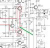
I think that short that happened is one marked green at picture below.
After the short amp went into protection mode.
The R453 is a wall of 1.8k that protects everything behind it from higher current.
And I suggest that let this current flow freely and some components there got damaged.

In the past it happened to this amp to be connected by mistake (yes, my mistake!) with one positive speaker output to the ground (right channel!). So at some high volume DAC connected to this amp died and the amp went into protection mode.
After turning in on I saw that idle currents went bad and since then I was not able to set any good values (below 3.5mV). I had it running on something like 4-5mV for some months (1-2 hours every day).

But now idle current went really bad. Same bad level as it was when one of Zener diodes was shorted.
I tested all Zener diodes again - all of them measure really high impedance (Mohms) and hold good voltage in diode mode measurement. So I think these are alive this time and something else is not that good :)


upload_2022-2-20_16-46-44.png
 
Last edited:
Just thought I'd post my experience with this amplifier here, hopefully it helps..

I bought one of these that was stuck in protection mode. Found that D111 and D311 on the vertical boards for L/R channels had both failed. That cured the protection mode issue but I was running into real problems setting the bias current too. The right channel seemed fine, but the left channel, trying to adjust bias did nothing until it would suddenly jump, and then the bias current on the right channel would jump up too.. and switching inputs also was spiking bias current, very, very odd.

I replaced the idle current trim pots, no difference. Replaced the 5V1 zeners D122, D133, D322, D323. No difference. Then I replaced all of the e caps in the power amp. No difference. Finally I tackled the low voltage regulator, replaced all the caps e caps there, and in the ISC circuit, and also a couple on the switch PCB behind the front panel. Voila! Problem sorted, and I'm thinking it was probably the low voltage regulator e caps that had gone bad - some of them looked very cooked, sitting as they do right next to the heatsinks on the pass transistors..

So, with these things, to save time, I'd suggest first replacing all the e caps in, at least, the low voltage power supply sections, and definitely anywhere else where temperatures are elevated.

This thing tested my patience, but the reward is a very fine sounding amplifier. Definitely much better than a C320 and C350 that have passed through my hands recently, both of which left me cold.
 
I found the C326BEE to sound the same as the C350, but I don't have your room, sources, speakers or ears.
 
I found the C326BEE to sound the same as the C350, but I don't have your room, sources, speakers or ears.
Yeah, I thought they had a very similar sonic signature tbh, but with my tiddly little speakers, the 326 just sounds a bit more organic and musical, and has a slightly fruity bottom end, reminiscent of the older stuff, which I tend to prefer - I'd take a 3020, 3130 or 3140 over any of the C320 / C350 / C326.. just my personal preference, and showing my age :)
 
Finally I tackled the low voltage regulator, replaced all the caps e caps there, and in the ISC circuit, and also a couple on the switch PCB behind the front panel. Voila! Problem sorted, and I'm thinking it was probably the low voltage regulator e caps that had gone bad - some of them looked very cooked, sitting as they do right next to the heatsinks on the pass transistors..

So, with these things, to save time, I'd suggest first replacing all the e caps in, at least, the low voltage power supply sections, and definitely anywhere else where temperatures are elevated.
have a very similar problem when I checked the idle current its fine on the right channel but on the left it starts around 3mv but then as it warms up the reading drops and wheni adjusted it suddenlty jumps up to 20mv on the left so somethings obviously amiss .
 
have a very similar problem when I checked the idle current its fine on the right channel but on the left it starts around 3mv but then as it warms up the reading drops and wheni adjusted it suddenlty jumps up to 20mv on the left so somethings obviously amiss .
I'd definitely look at changing e caps mentioned previously if you haven't already - looks like you're experiencing similar behaviour to what I found. It might also be worth changing the bias trim pots too, just in case (when I do that, I measure where they're set on removing the old ones, then pre-set the replacements to match; alternatively, to be safe, pre-set the replacements for minimum bias before fitting) I can't say I'm a big fan of these amplifiers - they do sound really good, but they run hot (almost 'designed to fail'), the power amplifier circuit is ridiculously complicated, and they're fiddly to repair with lots of surface-mount parts and daughter PCBs etc. Good luck!
 
OK GUYS. You did amazing and deserve some update from me.

It works.

It had been sitting on a shelf for several years. The world had forgotten about it. Eventually, out of curiosity, I decided to take another look at it. I repaired the paths that I had damaged while replacing the DC servo (TL071). I also ran a piece of AWG12 wire along the main ground connections. However, they were working anyway, so this wasn't actually necessary.

I checked the Zener diodes — all OK. I resoldered and tested the small transistor Q148 responsible for thermal compensation. I have no idea why they decided to place it on the underside of the main PCB instead of on the heatsink. The only devices mounted on the heatsink are Q160/Q360, configured with their collector-base junction shorted. Only the base-emitter junction is active.

Since there was no DC offset (still a steady 0 V at the amplifier output), I focused once again on the area around Q148. The resistors and voltages were all fine. However, I noticed a problem with trimmer VR103 (it should be adjustable from 0 to 200 ohms). Apparently, the wiper occasionally loses contact. It jumps to 200 ohms. While waiting for a replacement trimmer, I set it to maximum and shunted it with a 75-ohm resistor. The amplifier settled down and operated normally for a while (a few minutes). Then suddenly — bang — the voltage across the emitter resistors jumped from 3 mV to over 70 mV. Exactly the same fault as before.

I then focused on Q160/Q360, which plug into the main board. I noticed that when they are unplugged, the amplifier behaves exactly like this — a sudden jump to 80 mV or more. I removed them from the heatsink. Found nothing suspicious. Checked their hFE — within spec. I did notice, however, that the traces on the tiny PCB they are mounted on were very fragile. I swapped the transistors (left to right) and soldered everything properly.

I powered the amplifier up and... it works. The bias current is within specification. The heatsink is warm, but not hot.

The housing itself gets very warm. But interestingly, not above the main heatsink — it's hottest in the middle above the driver transistors and their individual little heatsinks. Yes, NAD is weird. Especially this C326BEE. At least now I finally have a chance to listen to it properly.

I must admit that when it first arrived years ago, it didn't impress us much. Perhaps because we had already become accustomed to generally good-sounding amplifiers such as Soneteer models. The blue LED was no longer enough to impress anyone. The NAD simply sounded decent and could play loud when needed, but it wasn't exactly a revelation.

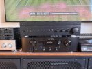
Now, after all these years, I'm listening to it again. Compared with the amplifier that eventually replaced it in my system (the Marantz PM7000N), it sounds rather disappointing. People used to praise its bass. Yes, it's punchy, but mainly because it doesn't extend particularly deep. Nobody ever praised the midrange or treble, and rightly so — they're largely absent.

The NAD presents music in a very generalized way. There is little detail and very little sense of space. On the other hand, it doesn't really matter whether the recording is good or bad — the NAD will simply play enjoyable music in a way that sounds like a competent Hi-Fi system. Nothing more, nothing less.

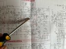
What really stunned me was a closer analysis of the schematic. It's a jungle of non-obvious interconnections. A message to alien civilizations: look how complicated something can be without actually sounding that good!

Thanks to everyone for the help.
 

Attachments

  • IMG_6644.jpg
    IMG_6644.jpg
    169.8 KB · Views: 4
  • IMG_E6639.jpg
    IMG_E6639.jpg
    160.2 KB · Views: 4
Update 2. Even more important.

After sorting out all auxiliary problems, which I described above, I have found a core issue.
My NAD was doing OK but only for around 15 minutes. Then id it did it again. 80 or more mV and hot heatsink.

But now field was clean. I knew where I was.

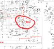
After some ordeal I have found it. Transistor p-n-p marked Q149 mounted on copper side. I applied cold air jet on it, and things return normal. No air jet - again the same issue. Used thin straw. When cooling down the case next to heat shrink wing - immediate positive result. This transistor is faulty. I am awaiting replacement in a couple of days. This is a core issue here. I'll let you know, when it is really over.
 

Attachments

  • powamp1.png
    powamp1.png
    288 KB · Views: 6
Back
Top Bottom