internauta20
New Member
Hi to everyone...
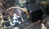
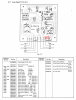
A few days ago I took on the task of rescue my old Nakamichi 700 II (1973-79) and the first thing I come across is a lack of 12 Volt output from the power supply PCB, the voltage It is not stable and varies randomly to such a degree that in the multiple measurements I made I registered 0. 4.5, 9.7,12.5, 13.2 and even 14.6 Vol. All of the above once you have tested the output of the corresponding winding in the transformer and checking that it is correct . In fact, the outputs that feed the vumeter bulbs are correct and they turn on when current is applied to the equipment.
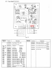
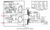
I am not a scholar on the subject, I checked the 8 main components of the 12vol stage, the rectifier package, the two transistors, the capacitors and the two resistors but still I cannot find the origin of the problem perhaps due to my inexperience in the subject of checks on components.
I am very grateful for the help of a good Samaritan who enlightened me about it and guided me to the right path to solve this little problem.
Please see attached images and sorry to google for the bad translation
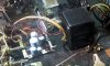

A few days ago I took on the task of rescue my old Nakamichi 700 II (1973-79) and the first thing I come across is a lack of 12 Volt output from the power supply PCB, the voltage It is not stable and varies randomly to such a degree that in the multiple measurements I made I registered 0. 4.5, 9.7,12.5, 13.2 and even 14.6 Vol. All of the above once you have tested the output of the corresponding winding in the transformer and checking that it is correct . In fact, the outputs that feed the vumeter bulbs are correct and they turn on when current is applied to the equipment.
I am not a scholar on the subject, I checked the 8 main components of the 12vol stage, the rectifier package, the two transistors, the capacitors and the two resistors but still I cannot find the origin of the problem perhaps due to my inexperience in the subject of checks on components.
I am very grateful for the help of a good Samaritan who enlightened me about it and guided me to the right path to solve this little problem.
Please see attached images and sorry to google for the bad translation