• The move to the new server is done. There are some software and database maintenance updates in process. This has us passing the hat around to help out. We appreciate any donations. Seriously, even a dollar helps. The payment page may be found here - https://www.audiokarma.org/support.html

Nakamichi RX-202 power issue

LedDuck

New Member
Hello there.
I know somebody posted this issue before, but I'm looking to gain some insight on how to resolve (if possible).
My RX-202 will power up for a split second (the tape counter lights up then turns off), then just the dB lights stay lit. Turning it off then back on does the same thing.
I replaced the voltage regulator (L78M12CV), but that didn't resolve the issue. For what it's worth, when I removed the old voltage regulator, it seemed like the solder came loose, and perhaps this was in fact the issue. Unfortunately it was not. :(
Before I start replacing part after part, can anyone recommend a course of action to take? Is there way to test voltage (using a multimeter) to know what it should be before and after a particular regulator? I have downloaded the service manual, but not really sure how to test what.
This deck is easily 35 years old, and has been sitting in a shelf in the basement for 20+ years. I was looking to sell it, so when I went to power it on (to see if it worked) I was bummed when it didn't power on. :(
Any insight would be appreciated.
Thank you.
 
Register to hide this ad
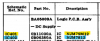
Hi Dankik, thank you for the reply. It does appear to be the exact issue as the link you referenced, but I couldn't figure out what to check. I have a multimeter, but didn't know where to put the leads. This should help. On the bottom picture, where you highlighted, this looks like a page from the servie manual. Where would I place the probes of the multimeter to check those voltages? Thank you again.
 
Where would I place the probes of the multimeter to check those voltages?
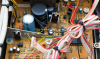
Here is a photo that I found of the Logic PCB. We will start by measuring the +12v, +6v, and -6v voltages.
  • Locate the connector FC-12, as shown in the photo. It is near the large black capacitor and metal brace. It should be marked on the board.
  • It will have a ribbon connector with 6 wires plugged into it.
  • I have numbered the pin numbers like the schematic. Pin 1 is closest to the metal brace. The voltages from the schematic are shown.
  • Set your multimeter (DMM) to measure DC volts.
  • Clip the (-) lead to the chassis (the metal brace shown as a place to clip the black lead).
  • Use the (+) red lead to measure the voltages of pins 4, 5, & 6. You might need a paper clip to poke into the connector to touch the contact read voltage.
  • So you don't short something out. Turn-off power, place the probes, turn on power and measure, turn off power, repeat.
  • Please list the voltages that you measure.
***CAREFUL*** - Don't short out to adjacent pins.
***CAREFUL*** - There is 120VAC nearby so be careful where you place your hands
.

upload_2023-2-15_8-37-24.png
 
Thank you!!! I will look at this tomorrow as the tape deck is in my office and I'm working from home today. As an FYI, I did replace the power regulator which is right above your yellow writing (Clip (-) probe here). Unfortunatley that didn't solve it. I will keep you posted on the voltages. Thank you again.
 
I replaced the voltage regulator (L78M12CV), but that didn't resolve the issue.
As an FYI, I did replace the power regulator which is right above your yellow writing (Clip (-) probe here).
If the regulator that you replaced is IC401 (circled in orange) and you replaced it with an L78M12CV, then I think you have changed the wrong part.
What is the PN on the old part that you took out?
  • According to the PL IC401 is the -12V regulator.
  • IC402 (attached to the chassis frame to the left of FC-12) is the +12V regulator.
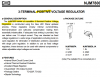
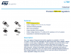
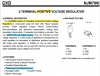
  • See datasheets below for the part descriptions.
Am I correct? Or did you replace IC402?

upload_2023-2-15_10-5-26.png

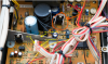
Are you talking about this regulator IC401? If yes, this is the -12V regulator.
upload_2023-2-15_10-9-50.png

upload_2023-2-15_10-8-21.png

The positive 12V regulator is the 2nd one:
upload_2023-2-15_10-11-48.png
 
WOW, the information you are providng is fantasic. I did in fact replac the regulator you circled in orange with a L78M12CV. One of my employees was helping me with this, so it's possible the wrong part was in fact ordered? I will look at the part number of the regulator we took out when back in the office tomorrow. I should be able to resolder it back into place if need be. When I'm in the office tomorrow, will telling you what the voltage is at each FC-12 pin help determine the issue? Thank you again for all of your insight and helping to troubleshoot. I am really just looking to sell it, which is why I powered it up after all of these years. A powered up device is worth more than one that doesn't power up. :).
 
will telling you what the voltage is at each FC-12 pin help determine the issue?
Yes. Provide the measured voltages for pins 4, 5, and 6 and...
Also, pin 3 of the negative voltage regulator IC401 after you replace it with the original. (Pin 3 is on the right per the photo above.)
If the measured +12V is bad (I think the other thread said they changed the 12V regulator), and the one you put in the wrong place is still good, then you might be able to use it to replace the 12V (if it is determined to be bad).
 
Hello Dankik. Here are the voltages from FC-12.
Pin 4: .56
Pin5: .03
Pin6: -6.29

Pin3 of the votage regulator was -12.13.

Hope this helps.

Thank you.
 
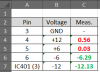
Thanks. Here is what you measured vs what it should be:
upload_2023-2-16_8-20-14.png
The +12V is bad and the +6 is bad. The negative voltages are OK. (I assume these were after you replaced the -12V regulator). IC401 is OK.

Before we replace the +12V regulator, I want you to check the output of IC402, the +12V regulator to make sure it is bad (or good).
DMM (-) to chassis ground like before and (+) to IC402 Pin 3 (as shown below)

upload_2023-2-16_8-34-46.png
 
Hi Dankik. I did in fact put the -12v power regulator back. When I test pin 3, I get a reading of .5v.
Does this help?
 
Yes, that means that the +12V regulator is bad. Do you have a +12V regulator available that you can replace IC402 with? If yes, go ahead and change it then re-measure Pin 3.
If the regulator is good, it should now read +12V. If that is good, then re-measure at FC12, pin 4 (+12V) and pin 5 (+6v).
 
Yes, what is the part number of that regulator? Is it a +12V? Unless you have another new +12V regulator.
 
The one that you put in by mistake is a L78M12CV. While it is 12V, it cannot handle the current.
upload_2023-2-16_9-40-56.png

The specs for the one that is in there is:
upload_2023-2-16_9-42-59.png

So you cannot use that old one.
Do you have a 1.5A, positive 12V regulator. Also, please verify the pin out is the same 1. In, 2. Gnd, 3. Out.
 
Back
Top Bottom