You are using an out of date browser. It may not display this or other websites correctly.
You should upgrade or use an alternative browser.
You should upgrade or use an alternative browser.
Near mint 500-C
- Thread starter RS Steve
- Start date


I'm sure it could if you continue to put your fingers on them, but they are in a location where you would seldom if ever need to.Will the Sharpie wear off. I'd love to put a mark on some of my controls because they are hard to see in a dimly lit room. I was thinking of pieces of thin pinstriping which come on a roll.

markd51
Nyuk Nyuk
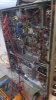
All cleaned and fully tested as working correctly. Eventually it will get new capacitors installed along with some typical upgrades, but for now, it's a completely working stock example of what a 500-C was back in the day.
View attachment 2795360
Purty! Kaspar at Stereo Rehab in Chicago has some of these doozies, but don't ask him to part with them! LOL
I think I'd love to own one, then let Kaspar go to work doing his magic. Probably knows them like his hand. You only live once.
https://stereorehab.wordpress.com/
Last edited:
I have just a couple here.Purty! Kaspar at Stereo Rehab in Chicago has some of these doozies, but don't ask him to part with them! LOL
I think I'd love to own one, then let Kaspar go to work doing his magic. Probably knows them like his hand. You only live once.
https://stereorehab.wordpress.com/


Yeah, my sharpie is permanent, but on metal it probably can wear off easily since it can't soak in.JHS... I believe there are Sharpies or other pens that are permanent ink that won't wear off.

Steve, you're gonna need to build another rack, at the rate you're going! 
Naah, some of the overstock has left the building, this one will replace the 500-C currently here since it's a tad nicer, and has documentation.Steve, you're gonna need to build another rack, at the rate you're going!

Steve, do you still have all those 1800's? 
(3)Steve, do you still have all those 1800's?

Masonavenut
I like old stuff
That absolutely amazes me. Weren’t most of them sold overseas? And you have 3??????? The Fisher Force is strong in this one!!
I used to have 4, but passed one on to a fellow AK member.That absolutely amazes me. Weren’t most of them sold overseas? And you have 3??????? The Fisher Force is strong in this one!!

So I got back to doing a full restoration on this receiver, installed screen and sampling resistors so I could further test things. I found the bias supply was running the tubes over .54V running on wall voltage even with a CL-80 installed. 
Now I will change out the original selenium rectifier, install HH can capacitors, and most likely individual balance and bias control to finish her up. I already replaced all the small lictic and the coupling caps, big 1.2K resistors, removed the AUX bleed circuit, and installed the jumper wire that ties both legs of the power switch together. Interesting that this receiver had a single Eurofoil as a coupler, and the other three were the black turd type. I took out and replaced all of them, checked the Eurofoil and it was spot on at .47uf still. Interesting that all the coupling caps were only rated for 400V, usually there are two that are bigger and rated for 600V. Everything looked 100% original, no sign anyone had ever been inside changing things. Can caps all measure a bit high from spec, but I always replace for the sake of reliability. While preparing to install the sampling resistors, I took the 1% ones that I have out of the bag and started testing to get 4 exact matching sorted out. My meter was showing they were all 17 ohm instead of 10 ohm. I tried one of my other meters, and it showed they were 10 ohm. Turned out to be the test leads for some odd reason, swapped the leads and the other meter showed 10 ohm. Just goes to show you, can't take anything for granted in testing.


Now I will change out the original selenium rectifier, install HH can capacitors, and most likely individual balance and bias control to finish her up. I already replaced all the small lictic and the coupling caps, big 1.2K resistors, removed the AUX bleed circuit, and installed the jumper wire that ties both legs of the power switch together. Interesting that this receiver had a single Eurofoil as a coupler, and the other three were the black turd type. I took out and replaced all of them, checked the Eurofoil and it was spot on at .47uf still. Interesting that all the coupling caps were only rated for 400V, usually there are two that are bigger and rated for 600V. Everything looked 100% original, no sign anyone had ever been inside changing things. Can caps all measure a bit high from spec, but I always replace for the sake of reliability. While preparing to install the sampling resistors, I took the 1% ones that I have out of the bag and started testing to get 4 exact matching sorted out. My meter was showing they were all 17 ohm instead of 10 ohm.
I tried one of my other meters, and it showed they were 10 ohm. Turned out to be the test leads for some odd reason, swapped the leads and the other meter showed 10 ohm. Just goes to show you, can't take anything for granted in testing.

Success, all the cans are replaced and the sound and output has really improved. This is certainly a nice time capsule sporting all original tubes except for the one 12ax7 that had a crack by the pins and turned cloudy. This is certainly the nicest 500-C I have owned, very pleased to add it to the museum.