• The move to the new server is done. There are some software and database maintenance updates in process. This has us passing the hat around to help out. We appreciate any donations. Seriously, even a dollar helps. The payment page may be found here - https://www.audiokarma.org/support.html

Need help from technicians and engineers

Naveed nasir

New Member
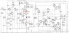
Power amp.jpg Screenshot_20200519-234207.jpg View attachment 1871744 Dear friends
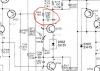
I wanna know the role of this marked 0.47uf/50v electrolytic capacitor . What 'll effect if I increase or decrease value,
Can I swap it with a ceramic or polypropylene ???
Any help and advise 'll be appreciated.
Thanks in advance
 
Last edited:
Register to hide this ad
What product is this a schematic for? It's impossible to read at such a small size. Do you have a higher resolution image we can look at?
 
Last edited:
That cap is feedback around that transistor. It has a timing constant associated with the resistor with which it is in parallel.

You can replace it with another type of capacitor such as a film cap, but changing its value is not a good idea.
 
Its ok to a replace a polar cap with a bi polar cap, not the other way around. Polypro is better than electrolytic, ceramic, polyester. Leave ceramic caps in tuners alone.
 
That cap is feedback around that transistor. It has a timing constant associated with the resistor with which it is in parallel.

You can replace it with another type of capacitor such as a film cap, but changing its value is not a good idea.

Thanks for your kind help.
 
Looks like it allows the amplifier bias to come up (relatively) slowly. It is possible it is also there to eliminate an instability that exist without it, but I think it is mostly to slow the increase in amplifier bias.
 
Looks like it allows the amplifier bias to come up (relatively) slowly. It is possible it is also there to eliminate an instability that exist without it, but I think it is mostly to slow the increase in amplifier bias.

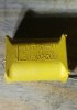
I also think so that it reduce the speed of bias transistor , but a strange behaviour of amp is seen when i change it with metal film of same value (I tried 2 types of metal film) shown in pic but every time I felt the sound stage became narrow and rumble in bass vanished , I could not understand this phenomena!!Screenshot_20200520-044701.jpg 20200520_044543.jpg
 
Since it seems a few knowledgeable people are here. Pardon my possible ignorance. I’m assuming -mv isn’t good on or off? In the picture the amp isn’t even on... jumps to -1v turning on or off. The two times I tested was around 20v

A299E5FC-D883-4652-AE05-07ABF25544C5.png
 
I was not testing the adcom. Sorry for being annoying and reviving but I see people that know more than I do....
 
A .47uF is awfully small for an electrolytic, as pictured on your schematic. I'd check to see what's actually in your equipment. If it's really a .47(also called 470 pF) you could replace with conventional cap of similar rating. I smell a mis-print in your tech manual. Others will confirm or correct me certainly.
 
470 pF is NOT .47 µF. That would be 0.00047 µF.

This is in the bias spreader and is there to slow the response of the spreader. Or to slow the initial startup of the spreader as mentioned earlier. There would be no bias at startup, so maybe this serves as a turn on mute to allow the rest of the circuit to stabilize before allowing the output transistors to turn on.The actual value is probably arbitrary and anything close would probably be ok. But, if it's good, why replace it?
 
That cap actually speeds up the bias transistor. It is there to bypass R114 so that it can quickly fill any junction capacitance that Q105 has. More typical design is to bypass the transistor completely using a cap from collector to emitter.
 
It would turn on the bias transistor which will turn off or greatly reduce the bias. But the time constant of that RC is only 7 milliseconds.
 
Last edited:
I would agree that the power up timing is likely the primary reason for it being there, considering the 15K ohm and .47uF timing comes out to about 142hz. So it will stabilize slightly quicker than a half AC cycle charge.
 
Last edited:
I don't really like the design of this amp much. There are better bootstrap amps out there. But I would find it real interesting to play around with different caps in that spot while hooked to a distortion analyzer.

I have a receiver with a bootstrap circuit and has no capacitors for the bias transistor. And it also thumps pretty loud on power up. I might try some caps on it to see if the thump changes. And then see if it also effects distortion.
 
Last edited:
Back
Top Bottom