• The move to the new server is done. There are some software and database maintenance updates in process. This has us passing the hat around to help out. We appreciate any donations. Seriously, even a dollar helps. The payment page may be found here - https://www.audiokarma.org/support.html

Need help getting rid of hum

thornev

Super Member
I've read back on several threads displayed when I did a Fisher forum search on "hum." Nothing with the exact same symptoms as mine. Here are the facts:

1. The hum volume in stereo mode is equal in both speakers i.e. it is centered in the stereo field.
2. The hum is present in stereo and mono modes.
3. The hum is present when AUX, PHONO and TAPE MON are selected even with no devices connected.
4. I poked around inside the chassis and did find a loose connection in the RIAA mod at tube V16. Before that the hum was significantly louder in one channel and soldering the loose connection resulted in the current facts.
5. The hum is present with no devices connected to any inputs and 2 dummy 8 ohm loads are connected to the speaker outs. The hum is present with a turntable connected to PHONO LOW.
6. The volume of the hum increases when the VOLUME is turned up.
7. The hum is not that loud with the VOLUME at 9 o'clock or lower, but at 12 o'clock the hum is quite loud. However, with headphones at low volume, the hum is annoying enough.
8. It is a 60 cps hum, not a 120 cps hum.
9. I have not tried tube swapping as I don't know which tubes might be the cause and I don't have replacements for all tubes.
10. I tried poking at various chassis components with a plastic pointer. Nothing struck me as suspect. With a multimeter attached and on volts DC, when I put the + lead near some chassis leads, the hum got louder. I don't know which leads they are.
11. The receiver is heavily modded. I can't say that the hum appeared only after any particular mod. I can't say the hum was there when I first bought the used receiver. I don't remember.
EDIT:
12. Important: I don't have the stock power & filter circuits. I have the SDS Labs power and filter board. In other words, I don't have the normal C91, C92, C97 nor C98 cap cans, nor CR6, R132, R149, C86 and a few other components that are replaced by the SDS Labs board.

After much reading I'm guessing this is a ground loop issue in the chassis - hum due to multiple ground points in the chassis. But then again I'm sure there are plenty of 500-C's with multiple ground points and no hum.

Anyone got any ideas about next steps to try? I do have a scope, a multimeter and soon will have a ST1000A signal gennie. I'm still learning to use the scope and gennie.

Thorne

PS - This was an interesting read:
https://www.americanradiohistory.com/Archive-National-Radio-News/NRN-1946-08-09.pdf
 
Last edited:
Register to hide this ad
Check R120 and R85 on the heater circuit. They need to be grounded, and if hooked to pin 5 on the output's (where the 10Ω cathode resistor goes to ground) you'll get a ground loop. disconnect them from pin 6 of the outputs and attach to nearest ground point.
 
Along with Larry's suggestion, I'd check the grounding of your SDS board. Might be a loop with multiple grounds.
 
Yep yer right...but was looking down the line if somewhere in the sys there might be some ground problem.

Q
 
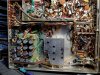
I'm attaching 2 images of my chassis as it is with the latest changes. Maybe someone can see something. You'll probably have to download them and use software to enlarge them.
 

Attachments

  • my chassis 2020-05-10- 2.jpg
    my chassis 2020-05-10- 2.jpg
    200.9 KB · Views: 39
  • my chassis 2020-05-10-1.jpg
    my chassis 2020-05-10-1.jpg
    207.2 KB · Views: 39
I've been avoiding it, but it's time for me to unscrew the SDS board and take photos underneath so I can see if anything at all from a stock 500-C remains. I doubt it as I was able to map most of the power and filter section components to those on the SDS board, but it's time to verify. I will post pictures probably tomorrow.
 
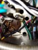
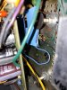
The SDS board is grounded to one of the C92 cap can chassis-attachment terminals (see the green wire). It's a big glob of solder (Picture attached). I've also attached a picture of what's behind the SDS board which I cannot completely remove without cutting a lot of wires.

EDIT: What I can say is that between the power transformer and the SDS board is an 8.2 ohm 5W 5% wirewound resistor. Also, R144 is present but inoperative. C103 and R149 are present under the board. R120 and R85 are under the board. R132 is missing but there's a ORG-VIO-YEL (370k) or RED-VIO-YEL (270k) resistor under the board which I cannot map to a stock 500-C's power section.

Something I found that might be the hum... The wire from the SDS board that powers the output tubes (i.e. connects to the daisy-chained pin 1's) came loose without pulling on it. Clearly it was not soldered. I pray that all the SDS board wires are not like that (the connections look like they are at least covered with those tubes you heat with a hair dryer) because soldering all those wires, disconnecting other wires so I can get to the SDS board wires and then reconnecting everything correctly is going to take days. And then if that's not the hum problem, you'll hear my screaming all the way to Jupiter ! :)
 

Attachments

  • 0512202355_HDR.jpg
    0512202355_HDR.jpg
    117.6 KB · Views: 24
  • 0512202351.jpg
    0512202351.jpg
    113.9 KB · Views: 24
Last edited:
Not sure what those two tan caps near the CL-80 (90? whatever) on the back of the power switch are to, but if they are audio signal and located too close to the AC wiring back there it might pick up some hum.
 
Gadget. IIRC one channel of the Phono circuit sits right there. It looks like the PEC may be partially or totally bypassed and left in.
 
Not sure what those two tan caps near the CL-80 (90? whatever) on the back of the power switch are to, but if they are audio signal and located too close to the AC wiring back there it might pick up some hum.
gadget and Larry... Those 2 tan caps are part of the RIAA mod. There are actually 3 caps and 2 resistors if we're talking about the same parts. There are 2 of those mods and they're connected to PC1 and PC2. That's where I was saying in a previous post there was a loose lead that I resoldered. Those printed circuits are for EQ and the mod was supposed to bring the receiver closer to the RIAA curve if I understood the mod correctly. The caps and resistors have to be attached to the PC's (which are still active) so I would have to add more wiring to move them farther away from whichever wires contain AC. If I add wiring to move them, I would think the new wiring would still be susceptible to the same AC signal. But maybe not because it's wire instead of components? I'd want to find what someone else's mod installation looks like so I can figure out where a good location would be.

EDIT: Although I'm glad the SDS board is there to make the receiver work, I would prefer to redo the entire power and filter sections so that I have access to all components in that area. I don't like that the board makes some parts inaccessible. I've seen some nice rebuilds in this forum of that area, but it's a little over my head without a schematic that would work given whatever else was removed for the SDS board. Expensive too probably.
 
Last edited:
I was just thinking physical proximity. If thats the selector switch (reminder, never worked on one of these) then having AC power switch bits physically close to that wiring makes it more inclined to pick up hum. In stock form I believe these had a "hat" over the back end of the switch to enclose all of it. Thats for shielding reasons and its not a bad idea. My Philharmonic chassis at least has the hat. I don't remember if the 600 does.

On the 600, the phono EQ PEC lives on the selector switch. I removed it completely and built a new board for that. Not sure how it would be done leaving the stock EQ in place unless its just doing tape head duty. I ditched the tape head part and converted that input to a second phono input jack. Made building the new board a little easier, 2 or 3 less components involved.
 
When I bought the receiver it didn't have the hat on the on/off switch. And the reason I put the CL-80 there instead of where the AC enters the chassis is that the SDS board makes it impossible to add anything that gets as hot as the CL-80 does. There's just no room around the SDS board.

There's a good 1 inch between the RIAA mod parts and the CL-80. I'll test if that's causing the hum by putting a piece of aluminum between the parts, see if the hum reduces. If so, then I will figure out a permanent solution. Thanks for the responses.

EDIT: I traced all the wires from the SDS board last night and documented to wherever they are attached. There is one lead that carries 160 vdc to the selector switch (via a t-strip that has other components attached to the same terminal), but it's on the other side of the switch from where the PC board resides. That's a good 2" away.
 
Check R120 and R85 on the heater circuit. They need to be grounded, and if hooked to pin 5 on the output's (where the 10Ω cathode resistor goes to ground) you'll get a ground loop. disconnect them from pin 6 of the outputs and attach to nearest ground point.
Those 2 resistors are under the SDS board. There's a lot of adhesive-backed thick padding covering those parts to prevent the board from shorting that I don't want to remove in case I don't get it put back perfectly. I've identified C86 under the board and it is connected to the SDS board. So I would guess that R120 and R85 are also active, but I can't see if there's wiring that goes from them to the output tubes.

That 8.2 ohm 5w 5% resistor that is attached to the power transformer and also to the SDS board looks like it might serve the same function as R142 in a stock receiver. Some kind of power conditioning.
 
Last edited:
Thanks, Rap.

But WHOA ! In that thread it states that V15 and V14 are reversed in 500-C later model on the Tube Layout page. That would also include the labels on top of the chassis. I found that the schematic has them reversed. But what I see in my later-model 500-C doesn't map to a reversed V14 and V15 inside the chassis. For example, the two .047 caps, C52 and C53, are indeed attached to what is labeled on top of the chassis as V15. Those 2 caps do not exist on V14. From what I'm seeing V14 is closer to the volume control than V15. I really need to get this cleared up as it affects a lot for me including my PHOTOFACT work.

Otherwise reading that thread was exciting because it does sound like my issue. I will certainly solder the 2 blue wires together off the t-strip. I'll report back. Thorne
 
Last edited:
If the hum is there in both channels with the volume full down -- when it should be utterly quiet -- my bet is it is due to how the IBAM circuit is installed. The grid return resistors for the output tubes should be located at the output tube end of the wiring between the tubes and the IBAM controls. Otherwise, the leads will pick up hum from the nearby power supply wiring. It may just be one of a group of things causing the overall hum, but it is certainly a element that should be corrected.

Dave
 
Back
Top Bottom