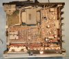
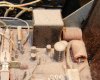
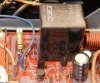
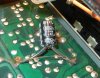
• The move to the new server is done. There are some software and database maintenance updates in process. This has us passing the hat around to help out. We appreciate any donations. Seriously, even a dollar helps. The payment page may be found here - https://www.audiokarma.org/support.html

Need Help Marantz 2252b Relay Getting Hot

dankik

AK Subscriber
Subscriber
Hi, I'm a new member in this forum. I have been reading all of your helpful responses for many years, but finally joined. I had a new Marantz 2230 when I was in college and sold it long ago.

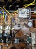
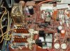
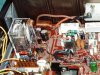
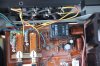
Recently I bought a used 2252b in working condition from Goodwill and recapped the electrolytic capacitors on the P700 Main Amp and Power Supply PCB, and main filter caps. I also replaced lamps with LEDs. The amp works after this. My question is: my speaker relay is getting hot to the touch. I think I have a voltage problem at the speaker relay (L703) coil. To debug, I tried replacing relay L703 with an Omron MY4, replaced diodes Q754 & Q746, and transistors Q743, Q744, & Q745, one at a time. Made very little difference.

Measured AC input to the board at J705 is 30VAC measured with a Fluke DMM, 80VAC p-p on a scope. I de-soldered the cathode lead of the rectifier diode Q754 and measured the voltage. On the scope, it is half-wave rectified and measures slightly less than +40VAC peak as it should, so diode is working. But, when I solder it into the PCB, I measure 34VDC at the relay input with the DMM (the schematic says it should be 23VDC).

I also measured the transistor EBC and the collector of Q745 is at 0.74V vs 3.1V shown on the schematic. One other thing, C740 (soldered to back of PCB is called out in the schematic as 10uF/50V but mine was 47uF/50V soldered to trace side of PCB from Q754 cathode to ground.

Anyone have any ideas of where the problem with the relay coil voltage is (or is this normal)? Suggestions?

Thanks again everyone.
 
Register to hide this ad
Good mystery! First of all, the 3.1V collector voltage doesn't make sense to me. As long as there's a good 0.6 plus volts on the base of the transistor it should be closer to zero volts. Here's a possible catch, The half wave rectified voltage off of Q754 is only lightly filtered by cap C740 so there will be quite a bit of AC voltage riding on it which may be "fooloing" the meter. The reason for a smaller cap is so that the relay will release quickly upon power off. The 30 volts of AC you measure, half wave rectified, would not yield a higher DC voltage after the rectifier. Your scope would yield some interesting info.

I have done a couple of these and the relay I used was Omron MY4-02DC24. Please verify that you used something similar and of the right voltage rating.

Good news! I have a 2252B here and will check it out when I get a chance. Forgot about that!!
 
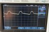
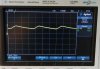
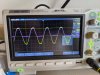
Hi, thanks. Yes I am puzzled?? First off the relay is an Omron MY4-02-DC24 (24VDC) which is a drop-in fit both mechanically & electrically. I lifted the cathode side of Q754 and put a scope probe on J705 and cathode side of Q754 (see attached scope photo). The yellow trace is the input on J705 and the pink is the cathode of the diode Q754. The scope shows that the diode is rectifying the input, but, if I trust the scope voltages is is 80V p-p on the input and half-wave rectified 40V on. So why does my Fluke only measure about 30VAC from J05 to J739 (GND) and 34.2VDC when diode is re-soldered into board. The Fluke is a "True RMS" meter so it should show 0.707 x p-p AC voltage (80VAC * 0.707 = 56VAC)?

I thought that it might be a grounding issue with my scope since the 2252b is a hot chassis, so I carefully hooked my scope ground to the chassis and did not use the probe grounds. One thing that I did try awhile ago was to use the scope math function to subtract probe 1 and probe 2 and did not connect the ground up at all. This gave me even stranger results. When I looked at the board input J05 both the signal and ground had sinusoidal signals in-phase on them, but when I looked at the cathode of the diode and the ground there was a phase shift between the two signals so the difference between the two were not correct???. I don't know if it was a scope issue, but that might account for the measured 34VDC measured signal after the diode.

Do you have any thoughts or does anyone in this Forum have any measurements on this 2252b receiver? Does anyone have a spec on this transformer secondary voltage?

Thanks again for any thoughts on the matter.
PXL_20210924_162446245.jpg .
 
rBukner: You've worked on other 2252b's, what is the value of electrolytic cap C740 solder to the back of the board? This filters the 1/2 wave rectified voltage after the diode. The schematic shows C740 = 10uF/50V, but what I had in my receiver was a 47uf/50V. Maybe my DC voltage is higher because it is 5x larger that the schematic.
Thanks again.
 
I hope to haul out the 2252B for a look today. Right now a Pioneer S-950 is sprawled out on the bench. Then I have to prepare a package and watch some football!!
 
Well, it's staring us in the face! Your 47uF on the back is open or disconnected! Here's the story in pictures...

DSCN1197.JPG
The 2252B was a tad dusty inside.

DSCN1198.JPG
The area of interest. Then I took it out to the garage and blew the loose dust out.

DSCN1199.JPG
Ah, much better! The 30Vac comes in on pin J705 from a blue wire. On this unit, the rect. diode feeds a cooked looking resistor, which measured 100 ohms. That then goes to the relay coil and the filter cap on the back.

DSCN1200.JPG
Here is that cap and is 47uF. There is no other cap on this circuit. It is swollen but working.

DSCN1201.JPG
I had the 80V p-p on the AC coming in, but this is the other side of the rectifier. Filtering action! Measures on my Agilent meter 27Vdc and about 7Vac as it should.

DSCN1202.JPG
After the 100 ohm resistor, which is the relay coil, is this which measures at 24Vdc and 3Vac. The "27.3" on the scope display is the trigger level.

The 100 ohm is dissipating just over 100mW so I guess old age and long running hours have combined to cook it's coating. So change out that 47uF and you should be good. I'd add the 100 ohms at 1/2 watt if I were you, just to be nice to the relay coil.
 
Thanks for taking time to measure the voltages. You are correct, the photo I posted was with the 47uF cap on the back disconnected so I could measure the no load voltage after the rectifying diode. I'll reconnect the diode and cap then check my voltages against your scope shots. What did you use for ground on your scope, ground TP on the board?
 
OK, this morning I re-soldered the rectifier diode back in and also soldered the 47uF cap on the back of the board.
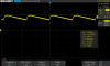
The output of my diode Q754 is 42V peak as shown on the scope. This doesn't look the same as your scope shot (while the peak voltage is the same, my RMS voltage would be higher because the cap decay starts at a higher voltage.
SDS00001.png

Measured at the same point using my Fluke and I get 34.7Vdc and 3.83Vac (vs your 27Vdc & 7Vac measurements).

PXL_20210927_164640181.jpg
I read your comment about the 100 ohm resistor, then compared your photo to mine. I don't have a100 ohm resistor in series with my diode! My schematic doesn't show this resistor either, but it seems to make sense to have this resistor there. So the voltage drop across that resistor could account for the extra voltage that I see at the relay coil. I'll buy a resistor and try it. Was that series 100 ohm resistor original to your 2252b? Thanks again.
 
...I don't have a100 ohm resistor in series with my diode! My schematic doesn't show this resistor either, but it seems to make sense to have this resistor there. So the voltage drop across that resistor could account for the extra voltage that I see at the relay coil. I'll buy a resistor and try it. Was that series 100 ohm resistor original to your 2252b?...

The 100ohm/1W resistor was a factory mod on this 2252b; it was replaced with a 100ohm/2W one during restoration.
2252b relay.jpg
2252b relay restored.jpg
 
Yep, it was factory and that 100 ohm was just as cooked looking as Leestereo's.

I just clipped the probe ground to the chassis - don't recall exactly where but it doesn't matter much in this case.
 
OK, today I added a 100 ohm/2W resistor in series with the diode and measured voltages with my Fluke:
  • After diode, before 100 ohm resistor: 28.89VDC, 6.35VAC
  • After 100 ohm resistor: 24.58VDC, 2.55VAC
  • Voltage drop across 100 ohm resistor: 3.3VDC, 5.59VAC
  • Voltage across relay coil: 23.8VDC, 2.53VAC
Much better. The resistor feels a little warm, but the relay temperature is warm but not hot now.

Here are the scope pictures after adding the resistor:
After the diode, before the resistor:
SDS00004.png

After the 100 ohm resistor:
SDS00005.png

That seems to solve the relay voltage. Quick check: FM works fine, but my AM radio only seems to picks-up static?? As I try to tune the static audio sound changes, but no music. I thought it was once working before I started troubleshooting the relay voltage.

Any suggestion on how to approach troubleshooting the AM? Looking at the P100/P200 schematic, I'm not sure where to start.

Thanks for your help.
 
***** Never mind. It turns out that the LED lights on my workbench caused the static ******

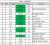
Trying to figure out why I now lost my AM reception. Q151 (HA1197) is the Hitachi AM Tuner chip used in the 2252b. I measured the DC voltages around the chip and compared them to the values in the schematic. Next I'll look at the signals with my scope, but I'm afraid that by probing, I may change the tuning and see nothing. I'm sure that it was working before, don't know what happened :(

voltages.png
 
Last edited:
Hi, I'm a new member in this forum. I have been reading all of your helpful responses for many years, but finally joined. I had a new Marantz 2230 when I was in college and sold it long ago.

Recently I bought a used 2252b in working condition from Goodwill and recapped the electrolytic capacitors on the P700 Main Amp and Power Supply PCB, and main filter caps. I also replaced lamps with LEDs. The amp works after this. My question is: my speaker relay is getting hot to the touch. I think I have a voltage problem at the speaker relay (L703) coil. To debug, I tried replacing relay L703 with an Omron MY4, replaced diodes Q754 & Q746, and transistors Q743, Q744, & Q745, one at a time. Made very little difference.

Measured AC input to the board at J705 is 30VAC measured with a Fluke DMM, 80VAC p-p on a scope. I de-soldered the cathode lead of the rectifier diode Q754 and measured the voltage. On the scope, it is half-wave rectified and measures slightly less than +40VAC peak as it should, so diode is working. But, when I solder it into the PCB, I measure 34VDC at the relay input with the DMM (the schematic says it should be 23VDC).

I also measured the transistor EBC and the collector of Q745 is at 0.74V vs 3.1V shown on the schematic. One other thing, C740 (soldered to back of PCB is called out in the schematic as 10uF/50V but mine was 47uF/50V soldered to trace side of PCB from Q754 cathode to ground.

Anyone have any ideas of where the problem with the relay coil voltage is (or is this normal)? Suggestions?

Thanks again everyone.
Wow I have a 2252b I bought new when I was a kid getting ready to attempt to Restoration my first sure could use some advice on where to start got a rebuild kit on eBay did not include the filter capacitors should I replace those to the guy I bought it from said they should be fine?
 
Hi Mud - Welcome as a new member. I'd be happy to answer any questions you might have on recapping my 2252b. To answer your question about replacing the main filter caps, when recapping the Main Amp & Power Supply Assembly (P700) you will need to remove the main filter capacitors anyway to get to the solder side of the P700 PCB so you might as well replace them while you have the receiver taken apart.

I ordered Nichicon 10000uF 50 volt radial caps P/N LKG1H103MKN from Mouser Electronics (Mouser #647-LKG1H103MKN) for $15.47 each back in June 2021. They are the exact same size as the original with solder terminals like the original. Some people were having difficulty finding a capacitor with the same dimensions as the original but this one matches and will fit in the mounting bracket.

Also, if you don't already have it, you should download the Marantz Service Manual with schematics, board layouts, and parts lists.

If you want to ask me more questions about your restoration, I would suggest that you start a new post in this Marantz forum so other members can respond to your questions also.
Thanks
 
Last edited:
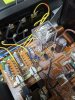
For the record, here is a photo of the completed 100 ohm resistor in series with the diode feeding the relay coil. The relay coil voltage is down to 24VDC. The 100ohm/2W resistor is sort of hot (~51C) and the relay coil generates some heat (~45C) measured with an IR thermometer, but not as hot to the touch as before and I am not over-driving
the relay.
PXL_20211003_192706704.jpg .
Thanks to rBuckner and Leestereo for your help and photos.
 
Hi Mud - Welcome as a new member. I'd be happy to answer any questions you might have on recapping my 2252b. To answer your question about replacing the main filter caps, when recapping the Main Amp & Power Supply Assembly (P700) you will need to remove the main filter capacitors anyway to get to the solder side of the P700 PCB so you might as well replace them while you have the receiver taken apart.

I ordered Nichicon 10000uF 50 volt radial caps P/N LKG1H103MKN from Mouser Electronics (Mouser #647-LKG1H103MKN) for $15.47 each back in June 2021. They are the exact same size as the original with solder terminals like the original. Some people were having difficulty finding a capacitor with the same dimensions as the original but this one matches and will fit in the mounting bracket.

Also, if you don't already have it, you should download the Marantz Service Manual with schematics, board layouts, and parts lists.

If you want to ask me more questions about your restoration, I would suggest that you start a new post in this Marantz forum so other members can respond to your questions also.
Thanks
Thanks been pretty busy lately actually had the nerve to finally tear into it ordered this daughter caps was supposed to get them today since I got in from FedEx must have gave them to the wrong house kind of afraid to tear into this thing I've had it since it was new found a couple things burn and it's burnt resistors I'll let you know how it goes I will start a new thread thanks for your advice will be in touch
 
Well I'm confused. Buddy brought a 2252B over and I thought I'd check for the 100ohm resistor and the cap. At R776 I've got what looks like a diode and tested .543/OL. Showed 33K ohms for resistance. Instead of a 47uf/50V cap on the other side of the board, I've got a 10uf/50V cap between J739 and one end of R776. Anyone know what's going on here?

Not a real early model, #U021095
EDIT: Also don't have a C740 in the parts list, though I have the cap on the back of the board.
IMG_1494.JPG
 
Last edited:
That is what mine originally looked like originally. Looks like the same diode as yours.
IMG_0970.JPG

The schematic does show Q754, a diode where the resistor symbol is. Somewhere in another thread it was mentioned that that might have been a change from an AC relay to a DC relay so the diode, Q754, is used as a half-wave rectifier. I can't see your relay part no in the photo. Is it a 24DC or an AC relay?

Screenshot 2021-10-10 190527.png
The reason I suspected something was that my relay coil was getting very hot and when I measured the voltage across the coil it was about 32VDC. rBuckner and Leestereo show a 100 ohm resistor in series with the diode so I added one and that dropped the voltage down to 24V and the coil is cooler now. You might want to check your relay coil voltage to see what yours is.
Screenshot 2021-10-10 193435.png

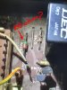
As shown in the photo at the top of this thread, I had a 47uF cap soldered to the back of the PCB. The schematic above shows a 10uF/50V for C740. It must have been increased for some reason. I don't know why, but I don't measure 3.1V at the collector of Q745 as shown in the schematic.

My build date (stamped on the chassis) is 19780429, which I assume is Apr 29 1978.
 
Last edited:
My relay is like yours, Type MS4U 24VDC DEC 067, I have the10uf/50V in the schematic, on the back of the board.

My build date is 9/22/1977

Tell me if I have this right. You blew away the diode at R776, and replaced it with a 100 ohm/2W resistor, and you have the 47uf/50 volt cap on the back?
 
Back
Top Bottom