

You are using an out of date browser. It may not display this or other websites correctly.
You should upgrade or use an alternative browser.
You should upgrade or use an alternative browser.
Need help picking a 2A3 SET design....
- Thread starter analog addict
- Start date

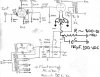

Something like this .... I'll do a little fiddling with PSUDII to get the power supply, but in the mean time, here is how the 2A3 filaments are connected. Pardon my extra sloppy 'paint' editing.
Thanks Micah!...:thmbsp:
What you see before you in all it's meager glory is my first attempt at putting together an amp design by the seat of my pants mostly. I need some help with the power supply to get the resistances right, along with the choice of choke.
If I understand this correctly, and that's by no means guaranteed, essentially it's V=IR, but I have to take into account the rectifier voltage drop, and the effective resistance of the choke in order to calculate the dropping resistors.
There's one more wrinkle in that I have an old chassis coming soon with 2 large chokes on it that may very well suffice for this design. And of course, the one meter that I don't own is some sort of inductance meter. However, I suppose I can measure the resistance of these chokes with my new trusty homebuilt blue ESR meter....

Suggestions? Comments? advice? Razzberries?.....


bricktop
Couch woofer
Let's see what we need here for a power supply:
+ about 8 mA for the plate current of the 6CL6
+ about 3 mA for the screen and divider
+ about 60 mA for the 2A3
----------------------------------------------
* 2 channels ~= 145 mA total at about 300VDC
Just a note, that since you are running the 2A3 with cathode bias, you'd want 250~260 VDC + the cathode voltage (about 48 volts) at the plate. Then, you'd need about 300VDC total (still perfectly fine with this power transformer).
To figure the worst case output ripple voltage (as if the triode plate was AC ground), you take the supply ripple voltage divided by the the transformer ratio. This supply has about 20.8 mV peak-to-peak ripple at V(I1), through you're 3K:8 transformer (Vratio = sqrt(3000/8) = ~19V) results in about 1.09 Vpp, or ~390 microVrms. (not bad) In reality, the triode has some AC impedance, so it will be better than this.
+ about 8 mA for the plate current of the 6CL6
+ about 3 mA for the screen and divider
+ about 60 mA for the 2A3
----------------------------------------------
* 2 channels ~= 145 mA total at about 300VDC
Just a note, that since you are running the 2A3 with cathode bias, you'd want 250~260 VDC + the cathode voltage (about 48 volts) at the plate. Then, you'd need about 300VDC total (still perfectly fine with this power transformer).
To figure the worst case output ripple voltage (as if the triode plate was AC ground), you take the supply ripple voltage divided by the the transformer ratio. This supply has about 20.8 mV peak-to-peak ripple at V(I1), through you're 3K:8 transformer (Vratio = sqrt(3000/8) = ~19V) results in about 1.09 Vpp, or ~390 microVrms. (not bad) In reality, the triode has some AC impedance, so it will be better than this.
Attachments
Thank you Sir...
I went and tried to duplicate your work, but wound up with some different numbers and a current limit warning......

I also tried it with a 5V4G, since I think that's actually the flavor of 5V4 that I have....

It also seems like some of the current numbers are higher. Am I missing something???....:scratch2:
I went and tried to duplicate your work, but wound up with some different numbers and a current limit warning......
I also tried it with a 5V4G, since I think that's actually the flavor of 5V4 that I have....
It also seems like some of the current numbers are higher. Am I missing something???....:scratch2:
bricktop
Couch woofer
I went and tried to duplicate your work, but wound up with some different numbers and a current limit warning......
Yea, you'll get a lot of warnings with PSUDII. It's because of the turn on surges. It does have a slow-start, but it's still way faster than the tube actually warms up and begins to pass current. As long as your steady state ratings are OK and you don't have a crazy huge cap right on the rectifier, it'll work fine.
I also tried it with a 5V4G, since I think that's actually the flavor of 5V4 that I have....
It also seems like some of the current numbers are higher. Am I missing something???....:scratch2:
Both the 5V4GA and the 5V4G are rated for 175mA DC current, and we're only pulling about 145mA avg. total. The numbers given in PSUDII on the left on your screen also include the start-up surges. Use the "after a reporting delay" with about 2-3 seconds to get the steady-state values.
Let's source some parts....
Taking a look at AES, they don't have a 12 H choke that seems to fit the bill.
They do have a 12H/100mA choke, but I'm not sure that's going to be stout enough....:scratch2:
I did find this....
FILTER CHOKE, ENCLOSED, HAMMOND, 10 H, 200 mA
P-T193J
Specifications
Rating: 10 Henries, 200 mA
Max. VDC: 800
Resistance: 82 ohms
Mounting centers: 2.5" x 2.44" vertical mount
Weight: 5.5 lbs.
(big sucker)
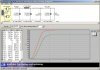
Which when plugged into PSUD gave the following graph....

Now please correct me if I'm wrong, but all I did was plug the stated resistance for the choke into the calculator, and then adjust R2 for 250V on the secondary load. There's also a 10H/150mA choke on AES, but looking at the current on it via the graph, its steady state was right at 150mA, and this one is cheaper, and can handle 200mA.
Am I doing this right?....:headscrat
Also, do I have to worry about the transient currents up to 0.7A across the choke? What wattage do I need for R1 and R2? I figure all the caps need to be 450V or better. Also would a small bypass cap on C2 be worthwhile?
Are we there yet????...
Taking a look at AES, they don't have a 12 H choke that seems to fit the bill.
They do have a 12H/100mA choke, but I'm not sure that's going to be stout enough....:scratch2:
I did find this....
FILTER CHOKE, ENCLOSED, HAMMOND, 10 H, 200 mA
P-T193J
Specifications
Rating: 10 Henries, 200 mA
Max. VDC: 800
Resistance: 82 ohms
Mounting centers: 2.5" x 2.44" vertical mount
Weight: 5.5 lbs.
(big sucker)
Which when plugged into PSUD gave the following graph....
Now please correct me if I'm wrong, but all I did was plug the stated resistance for the choke into the calculator, and then adjust R2 for 250V on the secondary load. There's also a 10H/150mA choke on AES, but looking at the current on it via the graph, its steady state was right at 150mA, and this one is cheaper, and can handle 200mA.
Am I doing this right?....:headscrat
Also, do I have to worry about the transient currents up to 0.7A across the choke? What wattage do I need for R1 and R2? I figure all the caps need to be 450V or better. Also would a small bypass cap on C2 be worthwhile?
Are we there yet????...
bricktop
Couch woofer
Taking a look at AES, they don't have a 12 H choke that seems to fit the bill.
They do have a 12H/100mA choke, but I'm not sure that's going to be stout enough....:scratch2:
I did find this....
FILTER CHOKE, ENCLOSED, HAMMOND, 10 H, 200 mA
P-T193J
Specifications
Rating: 10 Henries, 200 mA
Max. VDC: 800
Resistance: 82 ohms
Mounting centers: 2.5" x 2.44" vertical mount
Weight: 5.5 lbs.
(big sucker)
Which when plugged into PSUD gave the following graph....
Now please correct me if I'm wrong, but all I did was plug the stated resistance for the choke into the calculator, and then adjust R2 for 250V on the secondary load. There's also a 10H/150mA choke on AES, but looking at the current on it via the graph, its steady state was right at 150mA, and this one is cheaper, and can handle 200mA.
Am I doing this right?....:headscrat
Looks good to me. I had picked out a One-electron choke, but they are pricey, and probably only worth the cost for a choke-input supply.
Also, do I have to worry about the transient currents up to 0.7A across the choke? What wattage do I need for R1 and R2? I figure all the caps need to be 450V or better. Also would a small bypass cap on C2 be worthwhile?
Are we there yet????...
No need to worry about the transient. It won't be that bad in the real circuit. You can calculate the wattage by finding the steady state RMS currrent (using the "reporting delay" feature) and use P = I^2 * R. In this case, the resistor has about 235 mArms (notice that it is not our average ~145mA). Power would then be about 4.5 watts. I'd go with a 10 watt resistor to keep it cool. Doing the same for R2, you get about 1.4 watts. A 3 or 5 watt resistor would be good. Almost there :yes:
Roger that....
I'll work on drawing up the PS tomorrow and adding it to the driver circuit.....:thmbsp:
The other thing is I have two large chokes coming in on a trade deal. I don't know anything about them, although I suppose I can get the inductanceresistance measured one way or another. The big question is how do you measure/estimate the current handling ability????
I'll work on drawing up the PS tomorrow and adding it to the driver circuit.....:thmbsp:
The other thing is I have two large chokes coming in on a trade deal. I don't know anything about them, although I suppose I can get the inductanceresistance measured one way or another. The big question is how do you measure/estimate the current handling ability????
Here's another go....
...at a draft schematic....:scratch2:

...at a draft schematic....:scratch2:

heekma
Well-Known Member
Hey there AA,
When it comes to Lcrit, it's a matter of voltage/mA.
For example, I'm building a pair of 2A3 monos, I'm using the RCA manuals operating point of 250V @ 60mA.
250/60 (mA is assumed) = 4.16Lcrit.
Use your own plate/PSU voltage to calculate your Lcrit. Not written in stone, but it's a good starting point.
In this case, 4.16 is Lcrit. According to my math, generally speaking doubling that h is advisable to handle the largest current swings, so 8-10h is right in the ballpark.
As I said, just a guideline, not written in stone. Also to be taken with a very large grain of salt as I'm in the process of learning myself...:thmbsp:
Best,
John
When it comes to Lcrit, it's a matter of voltage/mA.
For example, I'm building a pair of 2A3 monos, I'm using the RCA manuals operating point of 250V @ 60mA.
250/60 (mA is assumed) = 4.16Lcrit.
Use your own plate/PSU voltage to calculate your Lcrit. Not written in stone, but it's a good starting point.
In this case, 4.16 is Lcrit. According to my math, generally speaking doubling that h is advisable to handle the largest current swings, so 8-10h is right in the ballpark.
As I said, just a guideline, not written in stone. Also to be taken with a very large grain of salt as I'm in the process of learning myself...:thmbsp:
Best,
John
bricktop
Couch woofer
Hey John, this is just a cap-input supply, so meeting critical inductance isn't necessary. With a different PT, he could have gone that route, but it makes the chokes much more expensive too.
Nice schematic, Allan! (Think you could make the font skinnier though?)
Just one afterthought, you may want to change the 0.22uF coupling cap to a 0.47uF. As it in now, the -3dB lower cutoff frequency is about 7Hz. Not bad, but to get a flat phase in the audio band, bumping it down to 3-4 Hz will help. My bad for suggesting that 0.22uF earlier.
Nice schematic, Allan! (Think you could make the font skinnier though?
)Just one afterthought, you may want to change the 0.22uF coupling cap to a 0.47uF. As it in now, the -3dB lower cutoff frequency is about 7Hz. Not bad, but to get a flat phase in the audio band, bumping it down to 3-4 Hz will help. My bad for suggesting that 0.22uF earlier.

Gary Kaufman
Well-Known Member
Just a few alternate opinions, intended in a friendly way :yes:
Trying to "shoehorn" a power transformer you have into a design isn't always the right approach. The power transformer is only a small portion of the cost you're going to shell out.
Dropping voltage in a power supply is the wrong approach imho. You want the LEAST possible resistance between the power transformer and your amplifier. I've always found the best approach is to use low-dc resistance chokes.
While I generally do prefer choke loaded supplies remember that they are load dependent and will act "cap loaded" with no current draw. You either need appropriate bleed resistors or make sure the output section will be drawing current right at turn-on. Make sure caps are appropriately rated for the max DC they might see if the supply acts as a cap loaded supply or you may see fireworks.
You can also use a choke loaded supply designed to deliver just under your desired B+ and then "tune" the voltage by adding a small cap before the first choke - often .22 to .68uf is all that it will take.
Don't use a cheapie choke for a choke loaded supply, and remember that the current ratings of your transformer are for cap loaded supplies. A cheap choke will buzz like crazy. This is where you want some nice vintage UTC or Thordarson iron, and rated for around 2x your intended current draw. Trust me, I've learned the hard way. You can also position the chokes in the ground line to minimize the insulation voltage stress.
I've built the Simple 6SL7-->45/2A3 design as well as the Micro Morrison designs that were suggested. Loftin-White and Micro Morrison DC coupled designs can be tricky to set up but the Micro Morrison does sound very good.
There is a Sound Practices article in issue 15 = "I never met a 2A3 I didn't like" By Joe Roberts that is a "must read" before you go further. The Sound Practices CD would be a worthwhile purchase as there are dozens of articles on the 2A3. Gordon Rankin's 2A3 circuit in the "Baby Ongaku" article (Issue 9) is another design worth considering and has great layout notes.
Enjoy!
- Gary (http://www.the-planet.org)
Trying to "shoehorn" a power transformer you have into a design isn't always the right approach. The power transformer is only a small portion of the cost you're going to shell out.
Dropping voltage in a power supply is the wrong approach imho. You want the LEAST possible resistance between the power transformer and your amplifier. I've always found the best approach is to use low-dc resistance chokes.
While I generally do prefer choke loaded supplies remember that they are load dependent and will act "cap loaded" with no current draw. You either need appropriate bleed resistors or make sure the output section will be drawing current right at turn-on. Make sure caps are appropriately rated for the max DC they might see if the supply acts as a cap loaded supply or you may see fireworks.
You can also use a choke loaded supply designed to deliver just under your desired B+ and then "tune" the voltage by adding a small cap before the first choke - often .22 to .68uf is all that it will take.
Don't use a cheapie choke for a choke loaded supply, and remember that the current ratings of your transformer are for cap loaded supplies. A cheap choke will buzz like crazy. This is where you want some nice vintage UTC or Thordarson iron, and rated for around 2x your intended current draw. Trust me, I've learned the hard way. You can also position the chokes in the ground line to minimize the insulation voltage stress.
I've built the Simple 6SL7-->45/2A3 design as well as the Micro Morrison designs that were suggested. Loftin-White and Micro Morrison DC coupled designs can be tricky to set up but the Micro Morrison does sound very good.
There is a Sound Practices article in issue 15 = "I never met a 2A3 I didn't like" By Joe Roberts that is a "must read" before you go further. The Sound Practices CD would be a worthwhile purchase as there are dozens of articles on the 2A3. Gordon Rankin's 2A3 circuit in the "Baby Ongaku" article (Issue 9) is another design worth considering and has great layout notes.
Enjoy!
- Gary (http://www.the-planet.org)
Thanks for the suggestions Gary. I'm not smart enough to be able to respond intelligently to your comments, other than I'ne pretty much decided to use the Edcor PS transformer suggested earlier.....
Here's the updated schematic.....

Here's the updated schematic.....
bricktop
Couch woofer
I see what he means. The transformer is not exactly the correct voltage for a 5V4, but Ecdor's tend to run big a low-dcr, so adding a bit of extra series resistance can help out with the abuse of the rectifier. Additionally, you can easily drop in other rectifiers then with a tweak of the resistor and still get the right voltage. (i.e. pretty much take that resistor out and use a 5R4). Or, you can take it out, leave in the 5V4, and be left with a few extra volts (gets about 320V instead of 300V) for some more power, if you're ok with the extra 2A3 abuse (like new tubes). Being cathode biased, it shouldn't change things a whole lot.