• The move to the new server is done. There are some software and database maintenance updates in process. This has us passing the hat around to help out. We appreciate any donations. Seriously, even a dollar helps. The payment page may be found here - https://www.audiokarma.org/support.html

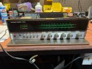
Need help repairing HK 330C

OK, I reinstalled the output transistors as well as the replacement diode and fired it up using the dim bulb tester. The unit came on without blowing a fuse. The light was not full but was still reasonably bright. I left the unit on for 10 sec or so and then shut it down. Where to from here?
Did it come on a bright for an instant and then dim down a little? Try checking DC offset at the speaker terminals.
 
the capacitors you tested dont look too clever .
Risen from the ashes!! I replaced the Caps and got a dim bulb when I turned it on so I fired it up normally and no blown fuses! Lots to still go through. Got a stuck meter for one and lots of scratch in the control knobs and switches. They will get a good cleaning today. With it up a running what are essential next steps?
 

Attachments

  • 330C.jpeg
    330C.jpeg
    185.7 KB · Views: 14
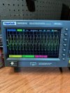
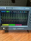
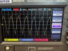
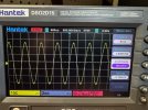
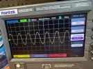
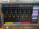
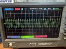
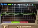
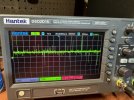
Thank you everyone for help to this point. I got the VU meter fixed, replaced the rest of the caps on the power board and adjusted bias. I get a nice stable balanced signal when inputting a 1000Mhz test tone through the Aux input ( picture attached). However, this is not the case when inputting the same signal through the phono input. The signal peak shows some asymmetry and it seems to be the same on on either the left or right input (pic attached). Any thoughts on what is likely causing this? Thank you!!
 

Attachments

  • 330C Aux section.jpeg
    330C Aux section.jpeg
    77.6 KB · Views: 15
  • 330C Phono section.jpeg
    330C Phono section.jpeg
    93.3 KB · Views: 15
What signal level are you putting into the phono stage? I can't read the scope screen too well but it looks like 1.68V (peak to peak)? That's way too much for any of your inputs really but especially way too much for a phono input. You may be overdriving it. An Aux input generally should be able to give you full output with about 150mV RMS input (about .425V peak to peak). A phono stage should give full output with about 2.5mV RMS input (about .007V peak to peak). A scope with a signal generator like it seems you're using will not usually go that low so you need an attenuator to get the signal down where it needs to be. Also phono stages use RIAA equalization so that's something to be aware of if you do a frequency response test. Your low freqs will be amplified much more than the higher freqs. Sorry if that's all stuff you know already but wanted to make sure you're not overlooking it.
 
Last edited:
What signal level are you putting into the phono stage? I can't read the scope screen too well but it looks like 1.68V (peak to peak)? That's way too much for any of your inputs really but especially way too much for a phono input. You may be overdriving it. An Aux input generally should be able to give you full output with about 150mV RMS input (about .425V peak to peak). A phono stage should give full output with about 2.5mV RMS input (about .007V peak to peak). A scope with a signal generator like it seems you're using will not usually go that low so you need an attenuator to get the signal down where it needs to be. Also phono stages use RIAA equalization so that's something to be aware of if you do a frequency response test. Your low freqs will be amplified much more than the higher freqs. Sorry if that's all stuff you know already but wanted to make sure you're not overlooking it.
I am completely new so this is super helpful and yes I am overdriving the input signal. My scope will only go down to 40mV (in 40mV increments) so I need to reduce the lowest setting by 16X to get down to 2.5mV. I am using a Hantek scope. What would you recommend? Thank you.
 
You can buy BNC attenuators that you can put inline between your signal generator and phono input. A 20dB one would knock a 250mV RMS signal down to 2.5mV RMS. Or a 30dB one would give you finer control of the output if you can only adjust in 40mV increments. That would give you 2.5mV with the generator set at 2.5V. These are all RMS voltages. Your generator may show RMS V if you change a setting but if not, be aware if it only shows peak to peak you'll have to convert my numbers.

Edit: Just thought to add that all this is at 1kHz. If you change the frequency, the RIAA equalization comes into play so if you drop the frequency down to 20Hz, the phono stage adds another 20dB of amplification and if you go up to 20kHz it subtracts 20dB so that may be an argument for having a few different attenuators to choose from so you can stay within the abilities of your generator while providing an appropriate input level to whatever you're testing.

 
Last edited:
You can buy BNC attenuators that you can put inline between your signal generator and phono input. A 20dB one would knock a 250mV RMS signal down to 2.5mV RMS. Or a 30dB one would give you finer control of the output if you can only adjust in 40mV increments. That would give you 2.5mV with the generator set at 2.5V. These are all RMS voltages. Your generator may show RMS V if you change a setting but if not, be aware if it only shows peak to peak you'll have to convert my numbers.

Edit: Just thought to add that all this is at 1kHz. If you change the frequency, the RIAA equalization comes into play so if you drop the frequency down to 20Hz, the phono stage adds another 20dB of amplification and if you go up to 20kHz it subtracts 20dB so that may be an argument for having a few different attenuators to choose from so you can stay within the abilities of your generator while providing an appropriate input level to whatever you're testing.
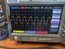
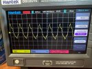
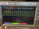
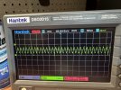
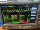
Thank you. As I am learning how to repair I am also learning my analytical tools. I figured out how to adjust the tone output signal to 2.5mV for the phono input and 150mV for the aux. The attached pictures show the left and right phono inputs at 2.5mV (1000 mHz), full volume. For reference the third picture is the aux (left channel only) at 150mV input at 1000 mHz also full volume. The phono signal does not look clean as compared to the aux signal but honestly don't know what is acceptable and what is not. Any thoughts?
 

Attachments

  • 2.5mV Phono Left.jpeg
    2.5mV Phono Left.jpeg
    213.8 KB · Views: 7
  • 2.5mV Phono Right.jpeg
    2.5mV Phono Right.jpeg
    209.9 KB · Views: 7
  • 150mV Aux Left.jpeg
    150mV Aux Left.jpeg
    211.3 KB · Views: 7
Try turning the volume all the way down and hooking your scope up to a tape loop output, not the speaker outputs, to test your phono stage. I think I've had this problem before and learned the hard way too. Hooking test gear and leads I think helps pass some 60 and 120 Hz into the phono stage input and because of that RIAA eq, those freqs get amplified a LOT and can cause your amp (and power supply) to act very badly. The standard way to test a phono stage is apparently using the tape outputs which will put out a line level (~150mV RMS) signal. It's still a mystery to me how phono stages work when you hook up a turntable to them :)
 
I looked at the 330C schematics and IF i understand them the difference between measuring output and the speaker terminal and the tape out terminal is that the later bypasses everything except the the equalization board. When I did this using an input voltage of 2.8mV (sensitivity of the 330C) I got the same looking signal shape as previous when monitoring at the speakers terminals (picture attached). This is useful because it isolates any influence of signal output to the equalization board. For grins and giggles I also looked at the signal output at 10mV, 15mV and 20mV (pictures attached) of input voltage. 10mV looks like 2.8. 15mV is cleaner with a little clipping and 20mV looks clean. What this suggests to me is that signal to noise at normal input values of an MM cartridge (3-6mV) is likely being compromised by noisy parts on the equalization board. Note, that saturation of the phono inputs occurs at 80mV according the the manual. I will likely pull the equalization board and start testing parts unless someone has another suggestion,
 

Attachments

  • Phono 25mV input.jpeg
    Phono 25mV input.jpeg
    135.1 KB · Views: 4
  • Phono 15mV input.jpeg
    Phono 15mV input.jpeg
    221.1 KB · Views: 4
  • Phono 10mV input.jpeg
    Phono 10mV input.jpeg
    154.6 KB · Views: 4
  • Phono 2.8mV input.jpeg
    Phono 2.8mV input.jpeg
    155.7 KB · Views: 3
I think you're on the right path. You can probably use your scope probe to trace the signal through the phono stage and you might be able to find the problem that way. Don't overlook the power supply circuit in the phono stage. Since your problem is on both channels, that can definitely indicate a power problem but once in a while it's the same problem in both channels.
 
So I finally had a chance to learn how and to trace signal through the phono stage.

The first thing I did was check voltages to the board. + voltage spec is 15.12 V and measured 14.6. - voltage spec is - 14.5 and measured at -14.25. Is the + rail voltage off enough to make a difference? Read on

When I tried to trace signal (1 kHz) at low input voltages of 10mA or less (input sensitivity of 2.8mV) it was near impossible to see anything above the noise at any spot on the board. At 15mA i could capture a noisy signal at the board output.

To convince myself that i could actually trace signal I raised the input voltage to 25 mA and you can see the results in the attached pics. The first is measured at the first capacitor. The second is the first transistor. Same level of signal as the first capacitor. The third is signal at the second transistor and is significantly amplified and then last is at the board output.

What is limiting the phono board from performing at the specified sensitivity input of 2.8mV. It seems to me that one or more of the board components is not at spec and requires higher input levels in order them to work. Should I pull caps/transitors and test them. Thanks in advance for any advise.
 

Attachments

  • IMG_1556.jpeg
    IMG_1556.jpeg
    149.2 KB · Views: 3
  • IMG_1555.jpeg
    IMG_1555.jpeg
    153.4 KB · Views: 2
  • IMG_1554.jpeg
    IMG_1554.jpeg
    145.9 KB · Views: 3
  • IMG_1553.jpeg
    IMG_1553.jpeg
    140.1 KB · Views: 3
Have you tried feeding the generator straight into the scope to see what that looks like? Were you feeding a 25mV peak-to-peak signal in? That's about what I see on your scope in the first pic I think. 25mV P-P is about 9mV RMS so your phono stage might not be working too bad here. I don't see the distortion you were seeing earlier.

I don't see much difference between your third and fourth pics. The output of both those looks to be about 1.4V peak-to-peak. That's around .5V RMS. Seems like plenty of output and looks fairly clean too. You may not have a problem?
 
So I most definitely confused the issue by inputting a signal of 25mV. That was really to show that I could trace it with a high enough input. Let me try to provide the right level of information as I understand it. And yes, it amplifies to a nice stable signal at the output of the phono stage with a high enough level of input signal. But, 25mV is well outside the output range of a moving magnet cartridge. Hopefully as you will see below the phono stage is noisy and maybe even not functional at normal moving magnet output levels.
My scope has a wave generator so that the source. The input value for voltage for the scope wave generator is Amplitude which by my understanding is 1/2 value of peak to peak voltage and the same as voltage peak (Vpk). The relationship between voltage peak and root mean square is Vpk = RMS X square root of two. The square root of 2 is 1.41 or Vpk=RMS X 1.41.

The input sensitivity of the phono section in my 330C is 2.8mV. I believe that like AC from a wall outlet that value is reported RMS. Most moving magnet phono cartridges out put between 3mV and 6 mV.

If I use the above equation knowing the RMS sensitivity of the phono input section is 2.8mV and solve for peak voltage (amplitude) - Vpk = 2.8mV X 1.41 I get 3.9mV. In theory I should be able to set the wave generator amplitude value at 3.9/4.0 mV and see a reasonably stable signal at the out of the phono stage. First pic is measured at the 1st capacitor and second pic is at the out put with the wave generator set at 4.0mV amplitude. Its all just noise. I tried amplitude values of 5mV and 6mV with no difference and then at 8mV I got the results in third and 4th pics. Its very noisy at the 1st capacitor but not as noisy at the output, but still not clean (similar to what was seen before at 10mV).

8mV peak/amplitude corresponds to an RMS voltage of 6.24 mV at the first capacitor before amplification and 110mV RMS after amplification at the phono section output. That equates to an approximate 25DB level of amplification. My understanding is that most phono stages will give about a 40-fold DB amplification.

The take away for me based on what I know and think have learned is that that the phono stage on my 330C would not work well with phono cartridge's putting out less than 7mV.

I wish I had a turntable to confirm all of this. Any suggestions on a good reliable used TT? I should probably have one if I am going to continue to do this. Is my rationale, correct? I'll not be offended it its off base. Should I start testing phono board components? Thank you!
 

Attachments

  • 4mV 1st capacitor.jpeg
    4mV 1st capacitor.jpeg
    205 KB · Views: 3
  • 4mV output.jpeg
    4mV output.jpeg
    212.7 KB · Views: 3
  • 8mV 1st capacitor.jpeg
    8mV 1st capacitor.jpeg
    230.8 KB · Views: 3
  • 8mV output.jpeg
    8mV output.jpeg
    176.2 KB · Views: 3
Ok, it does seem like your phono stage is a bit weak and noisy. If it looks the same in both channels I'd start looking at voltages to make sure they look correct everywhere the service manual / schematic gives you a value. When you have the same problem in both channels it's usually due to power. It could be bad components failing the same way in both channels but that's less common and the thing to check next.

Be careful getting a used TT since it introduces another variable you don't really need right now. If you had access to one that you know works well, it would be different. If you want a good working TT though, you might check Barter Town here on AK. You can find good stuff at good prices there.
 
Last edited:
.
It could be bad components failing the same way in both channels but that's less common and the thing to check next.
i had ceramic caps in both channels of an hk930 phono stage fail. not even the same position. i shotgunned them.

i wasn't expecting that but it happens.
 
Good advise on the TT. For all practical purposes its the same on both side and I know I have at least one bad cap that I tested yesterday on the left channel but the corresponding cap on the right side was OK. The cap in question is 10V 22uF aluminum. Can I substitute a 16V 22uF cap? It seems the latter are easier to come by rated at +/- 10%. Would +/- 20% work, or it that too much variance ( i can find those)

Also, in the circuit there are two transistors in each channel. One each 2SA844E (first one in the signal path) and 2SC1344E (second one in the signal path). When tracing the signal through the 844 on each side there is no amplification. All of the signal amplification comes at the 1344 transistor. I understand that the purpose of some transistors is to direct current flow but don't they also amplify? Is the 844 a possible source of the problem?

I'll also check voltages today. Best.
 
Going from 10V caps to 16V is going to be fine and most electrolytics are going to be +/- 20% tolerance so unless you see something in the parts list or schematic that indicates otherwise, you should be ok there.

2SC1344 are on the list of replace on sight transistors - https://audiokarma.org/forums/index...ilure-prone-whatever-and-replacements.731653/ so I'd replace those and it looks like KSC1845 works as a replacement.

The 844's could be a problem for sure. A quick search shows others have had problems with them before. If you want to get some replacements for the 2SA844 too, KSA992 will probably work but it might not hurt to get some KSA1015 just in case the 992's cause some instability.
 
This is very helpful. Thank you. I did not know there was a replace on sight transistor list!! That is a very useful reference. I have ordered some parts and will check back in once I have them replaced. I'll do one part at a time so I can check my work in case I make things worse.
 
It’s been a while on this project and it has not ended well. In my attempt to replace transistors on the phono board I seem to have disrupted the board pads to the point where I can not get solder to stick. Any suggestions?
 
It’s been a while on this project and it has not ended well. In my attempt to replace transistors on the phono board I seem to have disrupted the board pads to the point where I can not get solder to stick. Any suggestions?
Several options. You can use copper foil to reconstruct the traces and pads. Or if you're replacing the transistors you can leave the leads long and bend them along the trace that's left and solder to that. You may have to scrape away some solder mask to reveal the trace underneath.
 
Back
Top Bottom