• The move to the new server is done. There are some software and database maintenance updates in process. This has us passing the hat around to help out. We appreciate any donations. Seriously, even a dollar helps. The payment page may be found here - https://www.audiokarma.org/support.html

Need help - saving a botched QRX-5500A

JHint

New Member
EDIT; SOLVED! thanks everyone for your help

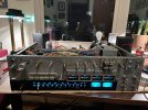
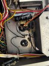
Hello! Reaching out for help as I try to save a QRX-5500A that was hacked by a bad tech before me: main problem - he clipped the filter caps and glued it new ones with long jumpers (see first photo)

Does anyone have any pictures they can share of how the filter caps for this are supposed to be wired? Or any insight on how filter caps should connect or on reading the schematics as I am not understanding

This poor unit also has weird missing components, many damaged solder pads, and yet still somehow works - hoping to bring her back to factory spec for another few decades of music - who doesn’t love seeing all those meters!
 

Attachments
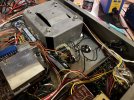
  • IMG_8121.jpeg
    IMG_8121.jpeg
    158.6 KB · Views: 39
  • IMG_8122.jpeg
    IMG_8122.jpeg
    238.5 KB · Views: 37
Last edited:
Register to hide this ad
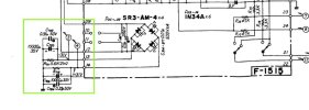
Perhaps these will help.

5500fc.jpg5500fcdraw.png
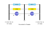
The schematic shows the little arrow bubbles labeled 3 and 4. Those are wires going to the power amps, they may have been connected to pins on F-1515 or they may have been connected directly to the filter caps. Based on experience they were probably soldered directly to the capacitor terminals.

Looking at your picture it appears they may have also hacked in a replacement for another chassis mounted cap shown here connecting to the + end to pin 6 of the F-1515.
Double check what I think I saw as it is not 100% clear that is the extra cap I see in your picture.

5500fc2.jpg
 
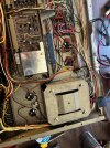
Here is a picture I took a couple of years ago of that area in my QRX-5500A. You may have to download the picture to zoom in on the filter cap area. Let me know if you need a clearer picture. I could open it up and take one.

IMG_1678.jpg
 
Here is a picture I took a couple of years ago of that area in my QRX-5500A. You may have to download the picture to zoom in on the filter cap area. Let me know if you need a clearer picture. I could open it up and take one.

View attachment 3796269
This is hugely helpful, thank you! He somehow left wires connected to one of the four original filter cap terminals but jumped the rest over to where the other chassis caps sit - this should help me at least get a start with the filter caps.
Is there any chance you have any pictures of the area under the other chassis caps to see how those are supposed to be wired in?
 

Attachments

  • IMG_8124.jpeg
    IMG_8124.jpeg
    313.6 KB · Views: 7
  • IMG_8125.jpeg
    IMG_8125.jpeg
    284.3 KB · Views: 7
Perhaps these will help.

View attachment 3796218View attachment 3796219
The schematic shows the little arrow bubbles labeled 3 and 4. Those are wires going to the power amps, they may have been connected to pins on F-1515 or they may have been connected directly to the filter caps. Based on experience they were probably soldered directly to the capacitor terminals.

Looking at your picture it appears they may have also hacked in a replacement for another chassis mounted cap shown here connecting to the + end to pin 6 of the F-1515.
Double check what I think I saw as it is not 100% clear that is the extra cap I see in your picture.

View attachment 3796227
This is amazing and a huge help, thank you! Yes you are right he hacked the other two chassis caps as well, and with jumpers going all over and some connected to one of the old filters terminals, this is very helpful
 
Hello! Reaching out for help as I try to save a QRX-5500A that was hacked by a bad tech before me: main problem - he clipped the filter caps and glued it new ones with long jumpers (see first photo)

Does anyone have any pictures they can share of how the filter caps for this are supposed to be wired? Or any insight on how filter caps should connect or on reading the schematics as I am not understanding

This poor unit also has weird missing components, many damaged solder pads, and yet still somehow works - hoping to bring her back to factory spec for another few decades of music - who doesn’t love seeing all those meters!
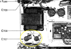
Looking more closely at your picture and the SM/schematic, those are not the filter caps that have been taken of circuit (C705/06) in your picture, but rather C707 and C708.

Screenshot 2026-07-06 at 9.39.51 AM.png
 
This is amazing and a huge help, thank you! Yes you are right he hacked the other two chassis caps as well, and with jumpers going all over and some connected to one of the old filters terminals, this is very helpful
Yeah, it does look like the filter cap in your picture (C706) has had the red wire cut. I guess instead of doing proper replacements, the previous person just cut wires to the old ones, and glued in new caps. :(
 
Looking more closely at your picture and the SM/schematic, those are not the filter caps that have been taken of circuit (C705/06) in your picture, but rather C707 and C708.

View attachment 3796282
I think it is both sets of caps. His images shows the socket for the PA assembly with the caps that are under it which I believe are C706 and C707.

5500ps3.jpg
 
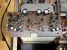
I found another picture showing part of C707/08 from the bottom. (I took the picture to document F-2048, but you can see the bottom of those caps at the top of the picture.)

IMG_1679.jpg
 
This is hugely helpful, thank you! He somehow left wires connected to one of the four original filter cap terminals but jumped the rest over to where the other chassis caps sit - this should help me at least get a start with the filter caps.
Is there any chance you have any pictures of the area under the other chassis caps to see how those are supposed to be wired in?
I don't have any more than those two, but should be able to open it up and take some clear photos of those areas later today.
 
I don't have any more than those two, but should be able to open it up and take some clear photos of those areas later today.
No further need! Thanks to your help and the schematic above, the filter and chassis caps have been corrected!

Before this update, the channels were uneven and had a loud background hum, which have both been solved with these caps in the correct array.

Thank you again for helping me save this one - now onto the rest of the rebuild!

IMG_8128.jpeg
 
I found another picture showing part of C707/08 from the bottom. (I took the picture to document F-2048, but you can see the bottom of those caps at the top of the picture.)

View attachment 3796284
That matches up perfectly with how I pieced together the wiring based on the manual and where the leads were attached on the glued caps - looks like we’ve got it!
 
Yeah, it does look like the filter cap in your picture (C706) has had the red wire cut. I guess instead of doing proper replacements, the previous person just cut wires to the old ones, and glued in new caps. :(
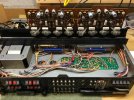
That’s correct - all four chassis mounted caps were bypassed and glued in with jumper wires - here they all are hanging out after I broke them free from the glue, before correctly wiring in new caps IMG_8126.jpeg
 
That’s correct - all four chassis mounted caps were bypassed and glued in with jumper wires - here they all are hanging out after I broke them free from the glue, before correctly wiring in new caps View attachment 3796310
Yikes, what a mess. Some people should not work on quality, complex gear like this. :no:

I just don't understand the idea of NOT putting replacements in properly. Seems like laziness to me...
 
Yikes, what a mess. Some people should not work on quality, complex gear like this. :no:

I just don't understand the idea of NOT putting replacements in properly. Seems like laziness to me...
I’d bet he just didn’t want to deal with fitting new new caps into the original clamps (as they were all smaller in diameter) - the replacements I put in were fitted specifically for this
 
No further need! Thanks to your help and the schematic above, the filter and chassis caps have been corrected!

Before this update, the channels were uneven and had a loud background hum, which have both been solved with these caps in the correct array.

Thank you again for helping me save this one - now onto the rest of the rebuild!

View attachment 3796306
There are a lot of "suspect" components in these, most notably 2SA726 and 2SC1312 transistors. Mine had static in any signal that went through the quad processing boards. Replaced all the transistors and most diodes on F-2048 and F-2084 before the problem was completely solved. Differential pairs on the driver board are 2SA726 also.
 
Back
Top Bottom