• The move to the new server is done. There are some software and database maintenance updates in process. This has us passing the hat around to help out. We appreciate any donations. Seriously, even a dollar helps. The payment page may be found here - https://www.audiokarma.org/support.html

Need help with 2230 Amp board (P750) troubleshooting

vferdman

Active Member
Hi, there. I have a 2230 on the bench that has a bad right channel power amp board. I have isolated the problem to it by injecting a 1kHz tone into the AMP IN terminals on the back. Left channel is fine and delivers about 35+ Watts of power on said test signal. Right channel is clipping the top part of the waveform even at the low levels of input. I have bad voltages on most points specified by the service manual. I have removed and checked all transistors and diodes including the thermistor on the heat sink. Everything checks out good. The board appears to be intact with no bad traces. The power supply caps have been replaced and are good. Any ideas or suggestions of what to try next? Output transistors are also good, BTW. This unit has mostly original parts in it still, save for the big caps and all the caps on the bad P750. I recapped it to start with, but it didn't solve the problem. I have rebuilt a few of these back in the day and they usually were pretty simple to get going again, but this one is fighting me.

Thank you in advance.
 
Register to hide this ad
So, you have an o-scope? That would be good and I can help you.
Yes, I have a scope and most things needed. I have a dim bulb tester, signal generator (app on the iPhone, but a really good one!). I've been around the block in industrial electronic labs when I was young. I learned a lot there. Operate an old CRT Tektronix 2246. Still does the job just fine.
 
I'm a little late getting up again after having eggs and toast for breakfast. Must have been the milk instead of coffee.

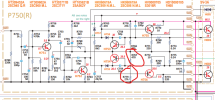
The (P750) R board, is it fully populated now? How did you test the transistors, especially H753, H755 and the output H001. While I wait for your reply I will study the circuit.
 
I'm a little late getting up again after having eggs and toast for breakfast. Must have been the milk instead of coffee.

The (P750) R board, is it fully populated now? How did you test the transistors, especially H753, H755 and the output H001. While I wait for your reply I will study the circuit.
Yes, the board is fully populated. I took each transistor, including the outputs out of the circuit and tested using multimeter. Nothing was shorted or open on the transistors. They all seem to test ok. (about 0.6V in one direction and open in the other). I may have missed something, though, so I am willing to re-test if necessary.
 
If you are able to power it up, with the 1kHz signal input, can you report what you see at H752 base and collector and the base and emitter on H755. In the service manual have you read, the clipping level adjustment? Did you change C754? I am wondering if the H753 transistor is leaking and taking down the positive half of the waveform with it. Can you list some of the Voltages you measured. I have to step out for about an hour so I will be back to read your explanation. Do your have a real transistor checker?
 
If you are able to power it up, with the 1kHz signal input, can you report what you see at H752 base and collector and the base and emitter on H755. In the service manual have you read, the clipping level adjustment? Did you change C754? I am wondering if the H753 transistor is leaking and taking down the positive half of the waveform with it. Can you list some of the Voltages you measured. I have to step out for about an hour so I will be back to read your explanation. Do your have a real transistor checker?
At base and collector of the H752 I see a clipped at the top sine wave. Same on base and emitter of H755. Adjusting the clipping with potentiometer does nothing. I replaced C754. H753 tests good. I used my multimeter as well as a FNIRSI component testing gadget.

Vltages on the first two transistors:

H751:
B 0.8V
C 6.3V
E 0.20V

H752:
B 0V
C 65V
E 0V

It already goes wrong at H752
 
Thanks for the update. We need to find how that 65V is on the collector of H752. R778, R766, R767 and R779 make up a Voltage divider. That should be ok. It is the transistor H755 that has the positive supply of 66.5 on it. The base of H755 should be at 30 Volts. The base of H755 is one diode drop below the base at 29.4 Volts. So at the junction of H755 and R765 there should be 30 Volts. Then the H005 you have two diode drops and back to the collector of H752. There should be the 28 Volts there. But if the transistor H755 was shorted, in wrong or the wrong device, Then the 66.5 Volt supply is connected to H005, the two stabistor diodes and through them to H752 and there is your 65 Volts. Check H755 please.
 
Last edited:
H755 is good. I also have bad voltages on the outputs. Something is clamping things to 65V all over the place. Emitter resistors are fine.
 
Please explain in a little more detail. You can remove the final and check the Voltages. When you say H755 is good, what are the Voltages on the base and emitter?
 
Please explain in a little more detail. You can remove the final and check the Voltages. When you say H755 is good, what are the Voltages on the base and emitter?
I am not sure what you mean by "you can remove the final". What final? H755 tests good when I remove it from the board and test it using a multimeter or a component tester. When I put it back in I get the following voltages on it. E 65.5V, B 66V, C 66.4V. This is with no signal present at the input, of course.
 
Thank you. What I meant by the finals were the output transistors. Too much radio work. I need to have my first cup this morning. Will be here.

Are you confusing the base with the emitter circuit on the board when making that measurement. Without H755 in the circuit, there is R770, a 10 Ohm resistor connected to the Positive rail of 66.5 Volts. That is what you should see at the emitter terminal. Refer to the schematic and you should be able to determine this.
 
Last edited:
Thank you. What I meant by the finals were the output transistors. Too much radio work. I need to have my first cup this morning. Will be here.

Are you confusing the base with the emitter circuit on the board when making that measurement. Without H755 in the circuit, there is R770, a 10 Ohm resistor connected to the Positive rail of 66.5 Volts. That is what you should see at the emitter terminal. Refer to the schematic and you should be able to determine this.
Yes, I did mix up the base and collector measurements, sorry about that. As for emitter terminal, I am still seeing 49V. Something is pulling the voltage down. Let me poke around...
 
Was H001, the output transistor in circuit when you made those measurements? I f it was damaged and leaking through the base/collector, you would see high Voltage at the emitter of H755.
 
Was H001, the output transistor in circuit when you made those measurements? I f it was damaged and leaking through the base/collector, you would see high Voltage at the emitter of H755.
I made measurements with and without both transistors. Here is the table of results.

With H755, with Outputs:
E 66.4
B 67.1
C 67.5

With H755, Without Outputs:
E 66.6
B 67.3
C 67.4

Without H755, with Outputs:
E 48.5
B 61
C 67.4

Without H755, without Outputs:
E 48.5
B 61
C 67.4
 
Measure across R767 and then one side of R779 to the other which goes to ground. I'm talking about the resistance. If any part of this circuit is open, it can cause the Voltages around H755 to go high. I'm hoping no other semiconductors are damaged. That 29V at the junction of R766 and R767 is important. That's what you should see if everything is copasetic.

1774378502030.png
 
Last edited:
Back
Top Bottom