• The move to the new server is done. There are some software and database maintenance updates in process. This has us passing the hat around to help out. We appreciate any donations. Seriously, even a dollar helps. The payment page may be found here - https://www.audiokarma.org/support.html

Need help with 2230 Amp board (P750) troubleshooting

Measure across R767 and then one side of R779 to the other which goes to ground. I'm talking about the resistance. If any part of this circuit is open, it can cause the Voltages around H755 to go high. I'm hoping no other semiconductors are damaged. That 29V at the junction of R766 and R767 is important. That's what you should see if everything is copasetic.

View attachment 3727334
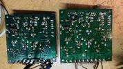
I checked all the resistors in that voltage divider. All good. I did take them out of the board. I understand that 29V in the center is absolutely essential for things to work. I am really getting a bit sick of this thing. I do have a parts board kicking around and I think I will just dust it off and try to use it after populating it properly (I pilfered a few parts off it in the past). It looks like the unit I have is a bit older and the silk screening is different on it from my other board. The board I am working on is all tan on the component side and the one I have in the parts bin is mostly green with much better graphics. They look the same as far as deign, though. Just the art is a bit different. I think the parts board is newer version. It has most parts in it save for the dual diode thing (this is one of the things I stole from it before) and a few other things that are simple to find. It's in good shape and I will try using it instead of the sick one.
 
I used another P750 board I had in the parts bin. It was missing a few components which I removed from the "sick" board. It was that double diode and a few caps. I replaced the bad board with this one and everything is working fine. I am still itching to find out what the heck was wrong, but honestly, I don't want to put more time into this thing. I tested most components in that board, visually inspected all the traces, etc. Just not able to find the fault. The replacement board seems a bit newer version. Has better silk screening on component side. Much clearer white on dark green instead of red on tan like on the bad board. Everything is working great and I am getting about 38 Watts per channel at 1kHz into 8 ohms. This is mostly original parts. Nothing has been updated except two 2200 uF caps on the power amp power supply (the ones that sit in a chassis). I'll probably try and look some more on the bad board to see if I can find the fault, but I am good to go on with this unit.

Thank you.
 
Last edited:
Here are the pictures of the two different P750 boards. One on the left (green) seems to be newer than the the one on the right (tan). There are subtle differences, but mostly they are the same. H757 diode is replaced with a thermistor and a resistor in series that is thermally coupled with the heat sink of H755 on the green board. On the tan board it was a regular diode not thermally coupled to anything. Silk screen and copper traces are the same. If anyone knows which one is more up to date, LMK. I replaced the thermally coupled thermistor (about 120 ohms at room temp and goes down to teens if I touch it with a soldering iron) with a regular 1N4148 diode. Works great. It is in series with the double diode thing that sits on the heatsink of the outputs, so thermally coupling it to the driver (H755) is kind of belt and suspenders, I think. Should be fine. Maybe it was some sort of redundancy for safety reasons.
 

Attachments

  • IMG_1976.JPEG
    IMG_1976.JPEG
    126.8 KB · Views: 6
  • IMG_1977.JPEG
    IMG_1977.JPEG
    130.5 KB · Views: 6
Back
Top Bottom