• The move to the new server is done. There are some software and database maintenance updates in process. This has us passing the hat around to help out. We appreciate any donations. Seriously, even a dollar helps. The payment page may be found here - https://www.audiokarma.org/support.html

Need help with an Pioneer SX-550

d_bolle

New Member
I have an SX-550 on my bench that I can't get to work. It lights up but the output is very weak and distorted on A or B. On headphones it's less weak when I don't select the channel with speakers connected to. I also tried the tape input as this doesn't go through the selector switch, but it's the same issue.

So far I have

* cleaned pots and switches, even gave the channel selectors 30 minutes to soak in Kontakt60 before flushing it with KontaktWL
* replaced the filter caps (with 8200µF 50V)
* replaced the two 5-pin SA798 with matched pairs of KSA992
* replaced about half of the caps in the amplifier assembly (none of which had a low resistance) and the two Sanyo 2sd313r (Q13 and Q15)

Does anyone know what the cause might be? I think I should now measure where the power is lost. But how to do that?
 
Last edited:
Register to hide this ad
Update: I noticed that the two 4A fuses in the center of the amplifier section are blown. I replaced them with 4A 250V fuses and also 6,3A 250V to compensate for the higher filter caps. Still they blow on turning on - what might cause this?
 
Last edited:
Unregulated supply fuses (4 Amp).
High probability, Shorted outputs.
Look there first.
You could use your meter in ohms or diode mode and go across the output transistor legs (Receiver NOT plugged in, NO power on) and look for the shorted ones.
If they are shorted, there will other components that were damaged. Hopefully its only one channel that has failed.

Build a DBT, (Dim Bulb Tester), Learn and understand its use. You will need this after the damaged components are replaced.
 
Last edited:
Unregulated supply fuses (4 Amp).
High probability, Shorted outputs.
Look there first.
You could use your meter in ohms or diode mode and go across the output transistor legs (Receiver NOT plugged in, NO power on) and look for the shorted ones.
If they are shorted, there will other components that were damaged. Hopefully its only one channel that has failed.

Build a DBT, (Dim Bulb Tester), Learn and understand its use. You will need this after the damaged components are replaced.
Thank you very much for pointing towards the output transistors. Then I will check those the next time I work on it. I was going to replace all 4 anyway, for which I will probably take that heatsink out (as it's very tricky to work on those 4 transistors when they are down there. But before desoldering, I will measure them with the DMM.

A DBT (aka Glühbirnen-Strombegrenzung) is definitely on the list, probably soon (latest before I work on a unit with blown fuses). And I will from now always check the fuses first before I do anything else.

Regarding the potential damage, what are parts that might be damaged by the high current/voltage? Transistors, electrolytic caps or even the smaller bipolar caps? The resistors look ok to me, nothing burnt there, at least to the bare eye.
 
Last edited:
Thank you very much for pointing towards the output transistors. Then I will check those the next time I work on it. I was going to replace all 4 anyway, for which I will probably take that heatsink out (as it's very tricky to work on those 4 transistors when they are down there. But before desoldering, I will measure them with the DMM.

A DBT is definitely on the list, probably soon (latest before I work on a unit with blown fuses). And I will from now always check the fuses first before I do anything else.

Regarding the potential damage, what are parts that might be damaged by the high current/voltage? Transistors, electrolytic caps or even the smaller bipolar caps? The resistors look ok to me, nothing burnt there, at least to the bare eye.
One thing to ask yourself the next time: why did the fuse blow, there is usually a reason. Once you think about that it is time to get out the DBT before you replace that fuse and turn it back on.

If the outputs are shorted then there may have been some upstream components that were damaged as well.
Check the driver transistors.
Check the emitter resistors on the output transistors.
Caps are not likely to be damaged.
 
Unregulated supply fuses (4 Amp).
High probability, Shorted outputs.
Look there first.
You could use your meter in ohms or diode mode and go across the output transistor legs (Receiver NOT plugged in, NO power on) and look for the shorted ones.
If they are shorted, there will other components that were damaged. Hopefully its only one channel that has failed.

Build a DBT, (Dim Bulb Tester), Learn and understand its use. You will need this after the damaged components are replaced.
finally had some time to continue working on the SX-550. I measured the output transistors, Q11 had a short from E to C, Q9 had shorts no matter how I measured, from EC, EB and CB. I replaced all 4 output transistors (Q9 and Q10 with TIP41C, Q11 and Q12 with BD244C). I measured them with the Fluke and no longer had any shorts.

As I had blown a few fuses already I figured there wasn't much more to destroy any more, so I plugged it in to see if the fuses are ok now. They are. But no sound on headphones, just crackle (I did have sound before I replaced the blown fuses a few weeks ago, so I definitely caused more damage by plugging in 2 pairs of new fuses) and something started smoking while I had it on today (d'oh, even more damage).

Guess I should already have built and used a DMB as was suggested.

So after doing that, I take it my next step is to take out and check all transistors of the driver and output stage? One question regarding driver stage and emitter stage: are these both on the same (left) PCB on the SX550, where the 4 large transistors are located, or is one of them on the right PCB with the tuner circuit, or even on the little PCB in the middle on top which is attached to the heatsink?

Sorry if this hurts to read, this is the first time I can't get an amplifier back to work by replacing a few parts and just firing it up again. But I guess I'm learning here for the next one. At least this one is not super rare. Still hope I will get it to work someday. If all else fails I have another SX-550 on my shelf which is really rusty in the back but seems to work ok, so I could just swap the entire board. But I'd really like to fix this one.
 
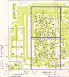
The amp channels are side by side on that one board. Note they are pretty much mirror images of each other.

550amp.jpg
 
When output transistors blow, they usually take out other stuff too. It sounds like it was only one channel that blew so you presumably have a good one to compare with. You'll probably be able to find shorted or open components just checking everything in-circuit and without powering it back on. It won't take that long to do diode checks on all the transistors and resistance checks on the resistors, looking mainly for open ones. Compare the bad channel readings to the good one if you see anything that seems off.
 
I like your determination.
But what's the hurry?
Enjoy the journey.
Build that DBT. It probably costs as much as the fuses you blew. It doesn't have to be fancy. You probably have all the parts you need to build it in your garage?
Yes, it takes a little face time using it to completely understand it's function and operation. It sounds like after this project you might need it again for another.
 
When output transistors blow, they usually take out other stuff too. It sounds like it was only one channel that blew so you presumably have a good one to compare with. You'll probably be able to find shorted or open components just checking everything in-circuit and without powering it back on. It won't take that long to do diode checks on all the transistors and resistance checks on the resistors, looking mainly for open ones. Compare the bad channel readings to the good one if you see anything that seems off.
That's what's weird, I neither have any sound left nor right.

Before I replaced the fuses I had weak sound on one side, but after that I don't have anything. So maybe something in the balance circuit blew as well. Anyway I will build a DMB and then check for open connections and replace the problematic parts.
 
That's what's weird, I neither have any sound left nor right.

Before I replaced the fuses I had weak sound on one side, but after that I don't have anything. So maybe something in the balance circuit blew as well. Anyway I will build a DMB and then check for open connections and replace the problematic parts.
A good rule of thumb is a problem that affects both channels is probably in the power supply. It's not always true but it ties into another rule of thumb which is always check the power supply first.
 
A good rule of thumb is a problem that affects both channels is probably in the power supply. It's not always true but it ties into another rule of thumb which is always check the power supply first.
So I tested all transistors and large resistors in the amplifier section. Transistors (Q1-16) were all fine. Resistors (R31-42, R47-49, R56) were also good.

What's odd is that R45 and R46 show drifting values, sometimes they start from 0 and go up to just below 500 Ohm, sometimes they start below 100kOhm and go downwards.
My multimeter is a Fluke 87V, set to either Ohm (12 o'clock) or diode test (1 o'clock), and shows DC on the top right.

To figure out the reason I checked the Diode D7-D10, and they also show this drift. The diode tester goes *bip* and sometimes *beep*, and the value shown on the display starts from 0.05 and rises. And this behaviour is showing both was, forward and backward measurement. Does this indicate broken diodes or is it caused be way the diodes are wired?

The diodes go directly to the fuses that blew before. Is it possible that these were damaged by the open transistor Q9?
 
Update: I took two fuses out and they measured fine. I guess my in-circuit measurement was affected by the way the four diodes are wired together.

Now I'm out of ideas - what might be a good next step?
 
The drifting values on those resistors are due to capacitors in the circuit. It's difficult to test things in circuit when there are rectifier diodes in there but at this point you're just looking for resistors which usually fail open and less likely, diodes that may fail either shorted or open. If you don't see anything obvious, you're probably ok to power it up on the dim bulb and check all the voltages coming from the power supply to see if they look normal. Some voltages may be a bit low while you're on the dim bulb.
 
Finally found time to work on this project again (I have it in a makerspace somewhere else and a toddler wouldn't let me go any earlier)

I tested radio with headphones, I didn't hear anything. I noticed that there was a bad solder connection on Q16 (in the power section). I resoldered that and now I have again music on one side. I guess I touched the transistor while working on the fuses and pushed it out.

The current status of the SX-550:
Sound on headphones only on one side
the fuses are burnt (not sure when that happened)
Q9 and Q11 do long beep on the multimeter (so they are open, right), whereas the other two give a short bip. But those transistors are new, I assume the issue causing them to be open is somewhere down the line.

At this point I would like to start with an oscilloscope and follow and compare left and right signal from the radio source to the output - and leave the fuses burnt for now.

Is this a viable strategy? Is it possible that an issue in the signal path could lead to the fuses blowing?

I also read somewhere people put in incandescent bulbs instead of fuses - basically a dim bulb tester inside the machine. Is that a useful strategy?

Thanks again for all the help!
 
You really need to sort the power supply out and make sure all the voltages coming from it are correct before moving on to things like signal tracing.

If you use a dim bulb tester, you can replace the fuses. The dim bulb tester will keep them from blowing again as long as you use a fairly low wattage bulb. I'd try a 40-60 watt bulb. I wouldn't try to wire bulbs in place of the fuses. It's possible but way more complicated than a simple dim bulb protecting the entire unit.

When the multimeter beeps, that indicates a short and not an open. If you're getting shorts on new transistors, there are a few options. You may not be testing them correctly, the transistors were not installed correctly and they're shorted to the heatsink, or there's something else shorted that's blowing them instantly which won't happen if you use a dim bulb tester.

When you're looking for big shorts, the usual suspects are the output transistors (which will probably take out other parts when they go). Sometimes it can also be the rectifier diodes or main filter capacitors.
 
Thanks for your reply. I built a dim-bulb-tester a few months ago and never got feedback on AK, and as I don't know where the fusebox is in that makerspace I was hesitant to use it.

Compact Dim Bulb Tester Wiring

Based on my engineering knowledge it should be fine, but maybe you could check it?

Regarding the bulbs in the fuse slots: I didn't mean to wire in light bulbs, I meant cylindrical incandescent lamps, as they are used in some pioneer devices as display light. like those:

Bitte entschuldigen Sie die Störung...

I would of course try to get some that are designed for the correct voltage.

I already replaced the main filter capacitors, the output transistors and checked the rectifier diodes before. Those should all be fine. I wondered if I put in the filter caps the wrong way (it's two huge cans in series) or made a mistake when changing the transistors with suitable replacements, but the problem was there before I replaced them, so the cause must be somewhere else.
 
I looked at your dim bulb tester and it looks ok to me. You don't need a fuse in the DBT and you want to keep the receiver plugged into the tester at least the first time you turn it on after replacing any parts or any time you're probing around in it. Only remove the tester after you know it's acting normally, which is usually a brief flash while the capacitors charge and then dimming down. The only times you definitely need to remove the tester are when you're setting the bias or measuring output power to see if it's in spec.

A 40-watt bulb should be enough for your SX-550. If the bulb doesn't dim much, try adjusting the bias to 0mv (turn the pot all the way down and make sure you don't turn it the wrong way). If the bias is set high you might get more glow from the bulb than you'd expect. Never try to set the bias to spec while the amp is plugged into the dim bulb tester. I always set the bias after I'm done working on everything and am confident in removing the tester.

I really wouldn't bother with bulbs in place of the fuses. Finding bulbs with the right voltage and wattage might be impossible and would be a lot of effort for no gain even if they exist in my opinion.
 
Back
Top Bottom