• The move to the new server is done. There are some software and database maintenance updates in process. This has us passing the hat around to help out. We appreciate any donations. Seriously, even a dollar helps. The payment page may be found here - https://www.audiokarma.org/support.html

Need PCB Software Advice

TriodeLuvr

So many electrons, so little time!
Subscriber
Most PCBs that I design for projects involve ICs and dozens of parts. I always have those made, usually at Express PCB. However, from time to time (like now), I want to cut a few small boards with five or six parts using my CNC mill. The CAD software that I use to generate CAM files used by the mill isn't generally workable for drawing PCB traces. However, it can import DXF, and I can use the shapes in the DXF file to create a cutting pattern.

The layout software provided by Express PCB can create a DXF file, but it only contains the board outline and the holes. The file doesn't show the traces. Maybe they do this on purpose, so users won't use their software to order boards from someone else. Or, maybe this is common to all PCB software that exports DXF. This is out of my field of expertise, so I don't know.

If someone here can point me in the right direction, what I'm looking for is basic, no-frills software that will layout a single-layer board with less than 50 or so pads. I don't need auto-routing, silkscreen capabilities or even a component library. What I do need is the ability to run this under Win XP, and it would be great to find a simple program that's freeware or shareware.

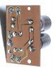
Here's an example of what I'm trying to do. This is a voltage doubler supply built for a preamp project. It took a long time to create the simple traces for this in the CAD software that I use for milling.

Any help with this will be appreciated!
PCB 01.JPG

PCB 02.JPG
 
Register to hide this ad
G'day...
Throwing darts here but did find a comprehensive list of winxp compatible freeware and share.. to examine. up to date? I don't know.
https://www.winsite.com/winboard/winboard+pcb+layout/

Thanks, I'll take a look. Turns out that I can create the board outline and hole positions with the mill CAD software, then export that as *.eps. Corel Draw will import it and keep the scale, but adding traces is tedious. Corel also doesn't weld the traces to the pads correctly. I just spent three hours discovering that. :( I also tried exporting DXF from AutoCAD to the mill CAD. It might work, but I haven't used AutoCAD in over 15 years. Seems I've forgotten everything I used to know. Another hour wasted. Darn, I was hoping to mill a couple boards like these today.


Isn't Eagle commercial software? Is there a source for freeware or shareware?
 
Thanks, I'll take a look.
I think you'll find something free as I saw a refs to cadcam and trace drawing capability combined.
(let us know, me for one, I like to know what you choose/ try out fav.

Q?? I'm curious how you will do the traces?
 
Thanks, I'll take a look. Turns out that I can create the board outline and hole positions with the mill CAD software, then export that as *.eps. Corel Draw will import it and keep the scale, but adding traces is tedious. Corel also doesn't weld the traces to the pads correctly. I just spent three hours discovering that. :( I also tried exporting DXF from AutoCAD to the mill CAD. It might work, but I haven't used AutoCAD in over 15 years. Seems I've forgotten everything I used to know. Another hour wasted. Darn, I was hoping to mill a couple boards like these today.


Isn't Eagle commercial software? Is there a source for freeware or shareware?

They used to have a free version, but it's been a while since I've used it. If you run Linux, there's a boat load of free software. I'm currently using LibrePCB and Fritzing for projects.

https://librepcb.org/

https://fritzing.org/

You might look at FreePCB, which is for Windows.

http://www.freepcb.com/
 
I'm working through everyone's suggestions. Eagle does have a free hobbyist version (nice), but it won't run on my 32-bit XP machine. FreePCB looks like just the ticket, but every link on their Website brings up "Sorry, this page doesn't exist." Continuing onward...
 
Check out Diptrace. The free version is exactly what you want and it's super easy to use.
 
G'day...
Throwing darts here but did find a comprehensive list of winxp compatible freeware and share.. to examine. up to date? I don't know.
https://www.winsite.com/winboard/winboard+pcb+layout/

I found DipTrace Free in that list, and it's is an excellent program. It also runs perfectly under XP. Unfortunately, the DXF output doesn't represent the traces correctly when I pull the file into CAD for the mill. The traces are just represented by hairlines. If I pull the DXF export into AutoCAD, it displays correctly. However, exporting as *.eps from AutoCAD produces an image in the mill CAD that's different still, and not useable for cutting a board.

I'm giving up on the concept of importing PCB files into my mill CAD software. There might still be a way to do this with Corel, but it will require more study. I've identified the issue regarding welding traces to pads. The question now is whether there's a workaround other than redrawing the entire board manually.

This was a useful exercise, even though the results weren't what I hoped. That happens sometimes, just nature of the beast. Many thanks to everyone who took the time to suggest things to try. I really appreciate your help!

Jack
 
I think you'll find something free as I saw a refs to cadcam and trace drawing capability combined.
(let us know, me for one, I like to know what you choose/ try out fav.

Q?? I'm curious how you will do the traces?

Luckily, these are small boards that I only need on a very limited basis, maybe once or twice a year. My only remaining DIY solution now is to export the mill CAD drawing as *.eps and open it with Corel. All the circles (pads) then need to be replaced in Corel with "primitive" objects in order for the weld function to work correctly. Weld is what connects the traces that I draw to the pads in a way that creates closed loops for the mill to cut around. Once the file is reworked like this, I can export back to *.eps and reopen in the milling software. It's more work than I wanted to do, but not a deal breaker for a couple small boards like this.

Not sure what you mean by doing the traces. I use a small CNC mill to cut the copper out in an outline around the conductors. Setting the depth to about .002" seems about right for this. After the board is cut, I smooth all the surfaces and install the components. The copper side then gets de-fluxed and sprayed with clear lacquer for protection. This is how the board in the image above was created.

Jack
 
I'm giving up on the concept of importing PCB files into my mill CAD software.
I found DipTrace Free in that list, and it's is an excellent program. It also runs perfectly under XP. Unfortunately, the DXF output doesn't represent the traces correctly when I pull the file into CAD for the mill.
I don't know the CAM format but I certain you need to convert DXF first.
does this help? or format it uses.
https://listoffreeware.com/free-dxf-to-gcode-converter-software-windows/
 
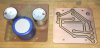
Thanks, I finished it in Corel just a few minutes ago (Yay)! Took less than an hour once I got the hang of it. Here's a screen shot of the side-by-side view in the mill CAD software. The drill pattern is on the left, the traces and pads are on the right. It's a simple matter now to cut a couple boards. These will hold the bias rectifiers and several filter caps for a pair of large monoblocks that I'm building.

211-Bias-PCBs.jpg
 
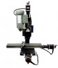
The mill CAD software can export to EPS. Corel can import and export that format. EPS maintains the scaling, so when I bring the modified drawing back, the dimensions are identical. I've been using a Taig "micro mill' for more than 10 years. I bought the "CNC ready" version, then added my own motors, a Gecko g540 controller and a DIY power supply. Below is the factory photo of a typical Taig CNC mill. I use it primarily for cutting and engraving aluminum chassis parts, including front and rear panels.


taig.jpg

This chassis started life as a heavy-gauge cake pan! :)

p4114641511.jpg
 
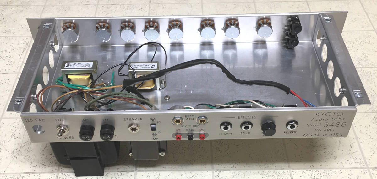
LOL, hope I didn't confuse the issue. The chassis above was finished several months back. It turned into a guitar amp that I gave my daughter. I built it into a gutted Peavey combo case that a guy on CraigsList was giving away. I'd been collecting parts for a guitar amp project for several years, and the empty case kicked me into overdrive. It's basically a Marshall 36 watt (2X EL34), but I added a vintage Accutronic spring reverb and effects loop. Speaker is a 12" from a Hammond organ, much better tone than the Chinese Peavey that was in the case when I got it. :)

Kyoto Amp 02.JPG

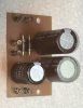
Here's the result of the mill work today. I'll press in the turrets and install other components tomorrow.

Bias Boards.JPG
 
Using mechanical cad S/w for pcb design has its limitations.
KiCad is a suggestion. I do not use it since I am fine with using orcad 16
Staying with WinXP is a problem with using current S/w
Of course there is a learning curve but in the end it usually well worth the time investment
 
Back
Top Bottom