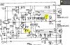
ANY HELP or GUIDANCE would be greatly appreciated - - My Onkyo 4500 MK II made a popping noise and I saw smoke. I took it apart and found the left channel was damaged - R518 smoked and R520 cracked open ( see attached file ) - I found that Q506 and Q506 are shorted E to C and R522 OPEN - I ordered the parts from Mouser and replaced them and powered it up - NO SMOKE

I checked the voltage at the speaker outputs ( ? DC Offset ?) and the right side is 2.5mv and the left side 6mv. The manual states to check and adjust the Idiling Current at test points ID and CT ( please the attached file ) and adjust at R517 to 40mv +- 10mv. I have 0mv on the left and is unadjustable - I checked the right side and have 45mv that can be adjusted.
The manual also states to check the Center Voltage and make sure it is +-50mv. The right side has 40mv and the left side is flucuating at 0 - 10mv. There is no mention of how to adjust this??
??? Any sugestions??? I hooked up speakers and they sound good.
I checked the voltage at the speaker outputs ( ? DC Offset ?) and the right side is 2.5mv and the left side 6mv. The manual states to check and adjust the Idiling Current at test points ID and CT ( please the attached file ) and adjust at R517 to 40mv +- 10mv. I have 0mv on the left and is unadjustable - I checked the right side and have 45mv that can be adjusted.
The manual also states to check the Center Voltage and make sure it is +-50mv. The right side has 40mv and the left side is flucuating at 0 - 10mv. There is no mention of how to adjust this??
??? Any sugestions??? I hooked up speakers and they sound good.