• The move to the new server is done. There are some software and database maintenance updates in process. This has us passing the hat around to help out. We appreciate any donations. Seriously, even a dollar helps. The payment page may be found here - https://www.audiokarma.org/support.html

Neglected RSb tune-up/rebuild. Crossover info.

Ben Bridges

New Member
I recently picked up an unmatched pair of infinity RSb's in somewhat rough shape, but all of the drivers work. I wanted to document a bit of the process I'm going through, seeing as these speakers are getting harder to find. Information on them seems to be disappearing from the internet too, so I will provide as much technical information as I can.
After getting them home I realized that one of the drivers didn't match. One was grey and the other translucent like I was used to seeing on infinitys. Looking closer at the cabinets, I could see that there were other minute differences and that I was likely dealing with one early production and one late production speaker, the grey one being early production. I was just happy to own them at all so I didn't mind. There was no noticeable difference between the midrange drivers. The EMIT font on the grey woofer speaker is a darker color, it is noticeably brighter on the translucent woofer speaker.
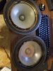
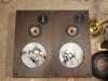
20210802_204347.jpg
20210814_191144.jpg
After getting the woofers refoamed, I cannot tell any difference between the sound of either. They have consecutive part numbers, 490781 for the translucent driver and 490780 for the grey driver. This confirms what I have read online, that the early production speakers have the grey driver, and that they should not sound different.

I looked into the crossovers. Online I have heard that some models have different component values based on what Infinity had available at the time, I was preparing for a struggle when rebuilding the crossovers. There were specs listed on some post that neither of my speakers match. Luckily both speakers match in terms of capacitor and inductor values (I think). One speaker has labeled inductors and the other does not, but between the two speakers each inductor has the same resistance. I am assuming that the inductance value should match as well. Here is what I have collected so far:

Caps:
16uF 100v
125uF 100v
7.5uF 100v
12.5uF 100v

Inductors:
2.0mH (measured 1.1ohm)
0.6mH (measured 0.6ohm)
0.1mH (measured 0.3ohm)
2.0mH (measured 0.2ohm)

L-pads:
Grey driver speaker-
tweeter L-pad: unlabeled, 0-2ohm measured
mid L-pad: unlabeled, 0-4.5ohm measured

Translucent driver speaker-
tweeter L-pad: labeled 5ohm, 0-2ohm measured
mid L-pad: labeled 5ohm, 0-2.6ohm measured

Grey woofer speaker crossover:
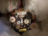
20210813_190117.jpg
Translucent woofer crossover:
20210815_104324.jpg
I was having trouble with one tweeter going out intermittently. I had to pull its L-pad out and disassemble it entirely. After cleaning that, I noticed the fuse holder was loose too. I bent the tabs in tighter and haven't had another problem yet.


This was my first time hearing the EMIT tweeter. I had been looking for almost 6 years to find some older infinitys that have the EMIT tweeter, they must be very uncommon in my area. They are exactly as precise and airy as I had been led to believe online. My next goal is to rebuild these crossovers with new components. Does anybody know the best way to remove the boards from the cabinets? I can see that they are glued and stapled in. Would it be worth it to try and screw them into the back of the cabinet similar to more modern speakers so that I don't have to remove a driver to get to them?
Also, would it be worth it to put in new L-pads as replacements for the old unmatched ones. It would make matching the left and right much easier, but the only parts available are 0-8ohm. I understand that I could simply find a setting that I like, and get resistors to match, but I know that I would be constantly doubting my choice of resistance/sound. Any advice would be appreciated.
 
Register to hide this ad
The mismatched woofers is not a surprise to me. Infinity did use both around the same time period. Now if they were consecutive serials numbers that might surprise me if OEM/as produced.
Could be one is a replacement installed by a previous owner. Give them props for not using a car "subwoofer" that just happened to fit the opening.
Infinity crossovers not matching each other or the "official schematic is also no big surprise.
The difference that stands out to me is that one has the yellow poly(?) cap Infinity used for the EMIT's. while the other has an NPE. Could have been a matter of substitution to keep the production line moving.
Doesn't look to me like either crossover has been changed from how it left the factory.
 
I wouldn't remove the crossover plates. Just if they feel loose. If not, I'd leave them alone and work inside the cabinet.

If you are talking about a complete cabinet restoration, that would be a different story.
 
I wouldn't remove the crossover plates. Just if they feel loose. If not, I'd leave them alone and work inside the cabinet.

If you are talking about a complete cabinet restoration, that would be a different story.
I would remove the plates if you want to do a complete restoration of the crossovers and they will need it. I don’t know how you would get to everything, solder, unsolder and place new parts along with tracing the circuits. The pots need to be removed, un-clipped and throughly cleaned and all the electrolytic’s cleaned. I have never seen an RSb with an NPE on the emits. Why even do anything if your not going to do it properly. Pull the staples and get after it. upload_2021-8-16_20-46-57.jpeg
 
If I did it again I would mount everything on a separate board and just use the plate for the pots and terminals. It’s almost impossible to fit the big polypropylene’s and the inductors aren’t positioned properly.
upload_2021-8-16_20-53-36.jpeg
 
If I did it again I would mount everything on a separate board and just use the plate for the pots and terminals. It’s almost impossible to fit the big polypropylene’s and the inductors aren’t positioned properly.
View attachment 2317070
BTW, I bypassed all the caps with a .01 PIO, why? Because I had a stash and wanted to hear the results. I added a rear firing identical emit as well with its own high pass filter and biamped. With the 1 1/2 inch laminated Baltic birch and bolted front baffle and reengineering mid enclosures, these reincarnated RSb’s sing like sweet love.
 
I would remove the plates if you want to do a complete restoration of the crossovers and they will need it. I don’t know how you would get to everything, solder, unsolder and place new parts along with tracing the circuits. The pots need to be removed, un-clipped and throughly cleaned and all the electrolytic’s cleaned. I have never seen an RSb with an NPE on the emits. Why even do anything if your not going to do it properly. Pull the staples and get after it. View attachment 2317065
I've worked on some RSb and a couple of Qb and Qa without problems, just removing the woofer. IMHO, removing the plate, which is glued and stapled, is not absolutely necessary to recap or rework the crossover. It's possible to work inside the cabinet without removing that plate. But of course, you can do it if you want.
 
I've worked on some RSb and a couple of Qb and Qa without problems, just removing the woofer. IMHO, removing the plate, which is glued and stapled, is not absolutely necessary to recap or rework the crossover. It's possible to work inside the cabinet without removing that plate. But of course, you can do it if you want.
Mine were just stapled. Pull the staples and they come right out. This allowed all the space needed to remove all the components, space things properly and install new binding posts and wiring. Tracing and copying the schematic, measuring the inductors and resistors. I applied cork gaskets and then drilled and screwed them back into place. If you are just replacing electrolytic’s sure, but to completely clean/restore and place new polypropylene caps, resistors, binding posts and tone everything out take them out and do it on the bench. But to each his own.
 
Hey everyone, thanks for the replies. I have redone certain aspects of speakers here and there before, but never to the extent I would want to take these. jefferylhenr, your thread was one of the first I read when trying to find info on these. A complete rebuild like that is exactly what I want to do, but I don't have quite the experience you seem to have lol! I have sufficient carpentry skills to confidently build cabinets and veneer them myself, but I live in an apartment right now so that wont happen too soon.
The crossovers are my main focus right now.

I have redone the crossovers on a set of 2-way bookshelf speakers before. These are a whole different beast and I probably need to read up more on crossover design to understand what I'm doing. I stared into the cabinets and over the course of an hour I drew up this rough schematic.
RSb_crossover_schematic_draft_1[1].jpg

I haven't drawn a schematic since high school, so don't be too critical haha. I drew more lines than necessary just to help me understand what is going on. I am confused about the inductors that bypass (is that whats going on?) the tweeter and midrange. I know of bypass capacitors and I see they are utilized here (right?), but I do not understand their function. I definitely need to do some reading.

I have a cart made on parts-express right now. I am planning on replacing all the caps with ones of equal value. Some I am going to have to put in parallel to get the right value. I am going to assemble all the components on a 5x7 board and run wires from the original crossover plates. Hoping I can get the inductors off of the original board.
The boards do seem to be just stapled in, not glued. I am not confident in removing them without trouble at the moment. I'll try at a later date.
For the L-pads, I am considering using resistors instead. The values don't currently match between the different L-pads. Before I commit to that, I am cleaning all 4 of them to find if the resistance values change and maybe eventually match. After cleaning the midrange L-pad on the grey woofer speaker, the values changed. The range is now 0.3-5.3ohm. I will share what I find. What I know now is that between the two speakers no two of the 4 L-pads are the same part.


The mismatched woofers is not a surprise to me. Infinity did use both around the same time period. Now if they were consecutive serials numbers that might surprise me if OEM/as produced.
Could be one is a replacement installed by a previous owner. Give them props for not using a car "subwoofer" that just happened to fit the opening.
Infinity crossovers not matching each other or the "official schematic is also no big surprise.
The difference that stands out to me is that one has the yellow poly(?) cap Infinity used for the EMIT's. while the other has an NPE. Could have been a matter of substitution to keep the production line moving.
Doesn't look to me like either crossover has been changed from how it left the factory.

goodolpg, the speakers were definitely not purchased together when new. The SN for the translucent woofer speaker is 121063. 7428230 on the grey woofer speaker. Yes that's right, one more digit on the grey woofer speaker, which I still assume to be the earlier production speaker of the two. One cabinet has veneer with a much more red color and the other more yellow/grey in tone. I can only imagine That the previous owner blew an EMIT and sourced an entire speaker? Its a pretty strange scenario and yes I am lucky there's no car subwoofers or generic woofer replacements involved here! Like I said I am very happy to have these at all.
 
Hey everyone, thanks for the replies. I have redone certain aspects of speakers here and there before, but never to the extent I would want to take these. jefferylhenr, your thread was one of the first I read when trying to find info on these. A complete rebuild like that is exactly what I want to do, but I don't have quite the experience you seem to have lol! I have sufficient carpentry skills to confidently build cabinets and veneer them myself, but I live in an apartment right now so that wont happen too soon.
The crossovers are my main focus right now.

I have redone the crossovers on a set of 2-way bookshelf speakers before. These are a whole different beast and I probably need to read up more on crossover design to understand what I'm doing. I stared into the cabinets and over the course of an hour I drew up this rough schematic.
View attachment 2323370

I haven't drawn a schematic since high school, so don't be too critical haha. I drew more lines than necessary just to help me understand what is going on. I am confused about the inductors that bypass (is that whats going on?) the tweeter and midrange. I know of bypass capacitors and I see they are utilized here (right?), but I do not understand their function. I definitely need to do some reading.

I have a cart made on parts-express right now. I am planning on replacing all the caps with ones of equal value. Some I am going to have to put in parallel to get the right value. I am going to assemble all the components on a 5x7 board and run wires from the original crossover plates. Hoping I can get the inductors off of the original board.
The boards do seem to be just stapled in, not glued. I am not confident in removing them without trouble at the moment. I'll try at a later date.
For the L-pads, I am considering using resistors instead. The values don't currently match between the different L-pads. Before I commit to that, I am cleaning all 4 of them to find if the resistance values change and maybe eventually match. After cleaning the midrange L-pad on the grey woofer speaker, the values changed. The range is now 0.3-5.3ohm. I will share what I find. What I know now is that between the two speakers no two of the 4 L-pads are the same part.


goodolpg, the speakers were definitely not purchased together when new. The SN for the translucent woofer speaker is 121063. 7428230 on the grey woofer speaker. Yes that's right, one more digit on the grey woofer speaker, which I still assume to be the earlier production speaker of the two. One cabinet has veneer with a much more red color and the other more yellow/grey in tone. I can only imagine That the previous owner blew an EMIT and sourced an entire speaker? Its a pretty strange scenario and yes I am lucky there's no car subwoofers or generic woofer replacements involved here! Like I said I am very happy to have these at all.
I had zero expectations when I started on the Reincarnated RSb’s. But dam if you listened to them now it takes your breath away. The cabinets and enclosure engineering can take good drivers and make them awesome. I didn’t go all out on the crossovers as I had no idea how far these drivers could go. Just take your time and have fun with it knowing you can end up with something really special. I have some ideas on how to do some external panels that could help the harmonics and a central internal brace out of 1 inch pvc as well. If you want to discuss ideas for the crossovers let me know. The rear firing emits really expanded the soundstage.
 
Inductors in parallel with the tweeter are part of the 2nd order high pass filter. You have 2nd order crossovers in that speaker.

An L-pad is made of 2 resistive elements. I think you have rheostats or variable resistors in your speaker.
 
I finally finished my crossovers and have made version 2 already.
The parts came in and I got to work, following my schematic and putting parts onto the 5"x7" board where I thought they would fit. I went with poly caps for everything because... well I didn't really think too hard about it. I understood that size was a consideration. Lets just say I have a more broad understanding of this now ;). I also understand that the benefits of the poly caps don't show off in the low range, but I thought it would be fun anyway.
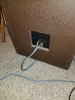
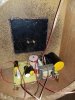
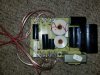
After cleaning the L-pads/variable resistors, I found that the median value for each was around 3 ohms. I thought the sound was fairly balanced and maybe a bit forward in the mids/highs at the middle setting, which was agreeable to my tastes. I substituted 3 ohm resistors for them in my new crossover. Everything would be wired with 16awg oxygen free copper wire. I had the board made and the circuits figured out, but had not considered how to connect everything. I chose to remove the old crossover boards entirely (which were stapled and glued) and replace them with 1/8th inch textured ABS panels. Each panel has new 5 way binding posts. I think the look is clean from the outside. For now they are held in with hot glue, which provides a good seal and hold to the cabinet. Anxious to hear the results, I just soldered wire to wire to wire until it was roughly together to get an idea of the results. With just the one speaker done it sounded very clear. I went into the next crossover with a better idea of what I was getting into.
20210828_203714.jpg
20210828_190136.jpg


I wanted to create something of a solder pad on the 5x7 perf board. I found strips of copper and cut them into 5 sections. + to the binding post, - to the binding post, and a + for each driver. There are still too many wires on the pads, since each driver has to ground to the same - pad as the circuits on the crossover network. Everything was arranged much better here, but I could still use more room. I'll probably skip the poly caps on the woofer circuit next time. These will be a work in progress for a while longer.
20210901_181500.jpg


But they are together. And they sound incredible! These are by far the best speakers I have ever heard. Everything is so clear and well presented. I need to make stands for them to get them off of the floor and into a bigger room. I am using a vintage Kenwood receiver (KR-5030) that is rated to be fine at 4 ohm. 60wpc at 8ohm and it plays them well. I was able to get an idea of their sound before with the old crossovers, but this is a massive step up. Speakers that I thought I liked now sound either veiled or shrill when I do an A-B comparison. These are so smooth and detailed. I want to sort out the crossovers, but I just want to keep listening.


While I had everything apart I noticed some other differences in the cabinets.
One has a midrange enclosure where the tube runs from the front baffle all the way to the back. While the other has a wider tube that does not go all the way to the back of the cabinet. A square piece of MDF is glued to seal the end of the wider tube. The volumes of each appear to be the same/similar at a glance.

One cabinet has a hole in the front baffle for the tweeter with a square piece of MDF glued on the inside. This forms a shallow inset cylindrical space for the tweeter. A hole is drilled in the square piece for the wires to feed to the tweeter. Putty was placed over the hole to seal the cabinet. On the other speaker there is simply a hole in the baffle the same diameter, but no square sealing it. You can see directly into the cabinet. A gasket seals between the baffle and metal tweeter plate.
20210828_190837.jpg
(The 16awg wire would not fit behind the tweeter on this cabinet)

And finally I discovered one difference between the crossovers. Each component was the same aside from the inductor on the woofer circuit. On the grey-woofer speaker, the inductance is 2.5mH. You can see in the pictures that one of the inductors is visibly labeled 2.0mH and the other is not. The label is actually on the bottom of the other inductor.

While I finalize the crossovers and mounting, I will try to make these cabinets match as much as possible. I plan on making new midrange enclosures, possibly out of PVC pipe. I will ensure the volumes match the originals. I will likely remove that block from behind the one tweeter so that both of those match. And I may even order a spare crossover as a source for a matching 2.0mH inductor. From my listening, I think that the cabinets could use more fill material so I am going to replace the old material and experiment with different amounts of polyfill.
 
Very nice. Can you rethink the placement of your inductors? They are way too close together. Basic physics, wire with an electrical current creates a magnetic field. Overlapping those fields with wound inductors basically couples them together magnetically. You have tons of room in there to space them out of each other’s phase.
 
I finally finished my crossovers and have made version 2 already.
The parts came in and I got to work, following my schematic and putting parts onto the 5"x7" board where I thought they would fit. I went with poly caps for everything because... well I didn't really think too hard about it. I understood that size was a consideration. Lets just say I have a more broad understanding of this now ;). I also understand that the benefits of the poly caps don't show off in the low range, but I thought it would be fun anyway.
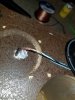
After cleaning the L-pads/variable resistors, I found that the median value for each was around 3 ohms. I thought the sound was fairly balanced and maybe a bit forward in the mids/highs at the middle setting, which was agreeable to my tastes. I substituted 3 ohm resistors for them in my new crossover. Everything would be wired with 16awg oxygen free copper wire. I had the board made and the circuits figured out, but had not considered how to connect everything. I chose to remove the old crossover boards entirely (which were stapled and glued) and replace them with 1/8th inch textured ABS panels. Each panel has new 5 way binding posts. I think the look is clean from the outside. For now they are held in with hot glue, which provides a good seal and hold to the cabinet. Anxious to hear the results, I just soldered wire to wire to wire until it was roughly together to get an idea of the results. With just the one speaker done it sounded very clear. I went into the next crossover with a better idea of what I was getting into.
View attachment 2336948
View attachment 2336947


I wanted to create something of a solder pad on the 5x7 perf board. I found strips of copper and cut them into 5 sections. + to the binding post, - to the binding post, and a + for each driver. There are still too many wires on the pads, since each driver has to ground to the same - pad as the circuits on the crossover network. Everything was arranged much better here, but I could still use more room. I'll probably skip the poly caps on the woofer circuit next time. These will be a work in progress for a while longer.
View attachment 2336949


But they are together. And they sound incredible! These are by far the best speakers I have ever heard. Everything is so clear and well presented. I need to make stands for them to get them off of the floor and into a bigger room. I am using a vintage Kenwood receiver (KR-5030) that is rated to be fine at 4 ohm. 60wpc at 8ohm and it plays them well. I was able to get an idea of their sound before with the old crossovers, but this is a massive step up. Speakers that I thought I liked now sound either veiled or shrill when I do an A-B comparison. These are so smooth and detailed. I want to sort out the crossovers, but I just want to keep listening.


While I had everything apart I noticed some other differences in the cabinets.
One has a midrange enclosure where the tube runs from the front baffle all the way to the back. While the other has a wider tube that does not go all the way to the back of the cabinet. A square piece of MDF is glued to seal the end of the wider tube. The volumes of each appear to be the same/similar at a glance.

One cabinet has a hole in the front baffle for the tweeter with a square piece of MDF glued on the inside. This forms a shallow inset cylindrical space for the tweeter. A hole is drilled in the square piece for the wires to feed to the tweeter. Putty was placed over the hole to seal the cabinet. On the other speaker there is simply a hole in the baffle the same diameter, but no square sealing it. You can see directly into the cabinet. A gasket seals between the baffle and metal tweeter plate.
View attachment 2337001
(The 16awg wire would not fit behind the tweeter on this cabinet)

And finally I discovered one difference between the crossovers. Each component was the same aside from the inductor on the woofer circuit. On the grey-woofer speaker, the inductance is 2.5mH. You can see in the pictures that one of the inductors is visibly labeled 2.0mH and the other is not. The label is actually on the bottom of the other inductor.

While I finalize the crossovers and mounting, I will try to make these cabinets match as much as possible. I plan on making new midrange enclosures, possibly out of PVC pipe. I will ensure the volumes match the originals. I will likely remove that block from behind the one tweeter so that both of those match. And I may even order a spare crossover as a source for a matching 2.0mH inductor. From my listening, I think that the cabinets could use more fill material so I am going to replace the old material and experiment with different amounts of polyfill.
If you can get your hands on raw sheep’s or scrap wool, you can mix it with the fill and it will tighten things up.
 
Back
Top Bottom