• The move to the new server is done. There are some software and database maintenance updates in process. This has us passing the hat around to help out. We appreciate any donations. Seriously, even a dollar helps. The payment page may be found here - https://www.audiokarma.org/support.html

New 76/12J5 Line Stage Preamp Build

kentuckycat

Active Member
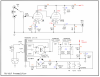
I'll be building preamp for my tube amplifiers very soon. I've ordered all of the parts and have received most of them already. I was looking for a low gain, line stage design and landed on the JE Labs 76/6SN7 design, which is the basis of the pre that I'll be building. I started shopping for the tubes and wasn't too happy with the price of the 6SN7's so I figured I go with the equivalent 12SN7 but the price on those is a little high, too. Then I shopped the single triad version of the same and found that 12J5 NOS tubes can be purchased for roughly five bucks each at AES. (by the way, the 76's look new and unused but the 12J5's - not so much. Glad I bought a few) So that's the direction I'm headed.
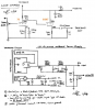
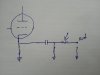
upload_2023-1-14_15-24-7.pngThe different filament voltages of the 6.3V 76's and the 12.6V 12J5's added a wrinkle to the heater supply since most of the plate and filament transformers are have 6.3V secondaries. Plus, this is a cathode follower preamp and the filament voltage needs to be elevated, so I was out of my league on this one. I dwelled on this for quite a while. A few AK'rs gave me some advice on the matter, too. Then I found a schematic from Vacuum Tube Valley for a 6SN7 or 12SN7 preamp with elevated filament voltage. They used a voltage doubler circuit and lifted the voltage for the filaments. Bingo!
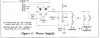
upload_2023-1-14_15-20-3.pngSo I'm scabbing that portion of their schematic into the JE Labs design, but again, I'm a little out of my league here. If anyone see's something wrong with what I drew up on the below wiring diagram, please let me know.
upload_2023-1-14_15-25-19.png
I've seen that most folks separate their power supply from the line stage but I wanted to keep them all together just because I've got limited real estate. I'm planning to incorporate a metal plate between the PS and the signal path inside the chassis. However, when the parts came in, the two Hammond chokes were larger than what I imaged, so when I when I was laying the parts out, it seemed like it would all be too crowded on the size chassis I was thinking about. Below I've got it laid out in standard Hammond 17x10 size. Does this layout look okay? Can the two chokes be oriented the same way or should I turn the one at the bottom/left 90 degrees?
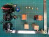
upload_2023-1-14_15-40-3.jpeg I haven't received the volume pot or input selector - so I just used place holders in the pic.
Any thoughts on any of this sure would be appreciated. I'll use this thread to document my progress, troubles, trials or tribulations as I go. Looking forward to hearing your opinions. Thanks, Jeff
 
Register to hide this ad
nice project
i didn't get into the particulars of the schematic, but consider adding a 100-200ohm resistor in series on the output, to avoid any potential stability problems, it's generally a good idea with cathode followers

do try to position the chokes at 90deg related to pt and each other if possible (maybe place one choke on the side of the chassis?)

1673777356612.jpg
 
nice project
i didn't get into the particulars of the schematic, but consider adding a 100-200ohm resistor in series on the output, to avoid any potential stability problems, it's generally a good idea with cathode followers

do try to position the chokes at 90deg related to pt and each other if possible (maybe place one choke on the side of the chassis?)

View attachment 2767659

OK, 90 degrees on the chokes, I wasn't sure about that one so thanks.
I like the idea of lower gain with the 37s but I've already purchased and received all parts.
On the 100R resistor at the output, I haven't seen that on the JE Labs design its predecessor, the Bruce Berman 76 line stage. What would would occur during an instability event? I'm assuming that would need to be a high quality carbon film resistor in that spot.
 
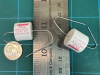
I wanted to make sure I'd buy decent coupling caps for this project. The schematic calls for .22uF 400v. I purchased Mundorf .22uF 450V caps and was expecting something bigger that what I got. These are about the size of mini-marshmallows that you might toss into a cup of cocoa. Am I missing something here?
upload_2023-1-15_10-31-21.png
 
What would would occur during an instability event? I'm assuming that would need to be a high quality carbon film resistor in that spot.

oscillations can occur, depending on the capacitance it will "see" at the output.
grid stoppers are useful too.
good quality parts are always desirable (no snakeoil bs:biggrin:)
 
I'll be building preamp for my tube amplifiers very soon. I've ordered all of the parts and have received most of them already. I was looking for a low gain, line stage design and landed on the JE Labs 76/6SN7 design, which is the basis of the pre that I'll be building. I started shopping for the tubes and wasn't too happy with the price of the 6SN7's so I figured I go with the equivalent 12SN7 but the price on those is a little high, too. Then I shopped the single triad version of the same and found that 12J5 NOS tubes can be purchased for roughly five bucks each at AES. (by the way, the 76's look new and unused but the 12J5's - not so much. Glad I bought a few) So that's the direction I'm headed.
View attachment 2767148The different filament voltages of the 6.3V 76's and the 12.6V 12J5's added a wrinkle to the heater supply since most of the plate and filament transformers are have 6.3V secondaries. Plus, this is a cathode follower preamp and the filament voltage needs to be elevated, so I was out of my league on this one. I dwelled on this for quite a while. A few AK'rs gave me some advice on the matter, too. Then I found a schematic from Vacuum Tube Valley for a 6SN7 or 12SN7 preamp with elevated filament voltage. They used a voltage doubler circuit and lifted the voltage for the filaments. Bingo!
View attachment 2767144So I'm scabbing that portion of their schematic into the JE Labs design, but again, I'm a little out of my league here. If anyone see's something wrong with what I drew up on the below wiring diagram, please let me know.
View attachment 2767151
I've seen that most folks separate their power supply from the line stage but I wanted to keep them all together just because I've got limited real estate. I'm planning to incorporate a metal plate between the PS and the signal path inside the chassis. However, when the parts came in, the two Hammond chokes were larger than what I imaged, so when I when I was laying the parts out, it seemed like it would all be too crowded on the size chassis I was thinking about. Below I've got it laid out in standard Hammond 17x10 size. Does this layout look okay? Can the two chokes be oriented the same way or should I turn the one at the bottom/left 90 degrees?
View attachment 2767191 I haven't received the volume pot or input selector - so I just used place holders in the pic.
Any thoughts on any of this sure would be appreciated. I'll use this thread to document my progress, troubles, trials or tribulations as I go. Looking forward to hearing your opinions. Thanks, Jeff
Looks like you've put a lot of thought into this so it should turn out really nice. Deciding on a layout is always the most tedious part for me.

Low gain really makes a lot of sense since most amps don't need any gain at all to produce full power. Yet I've found that having an active tube stage is a step up sonically from going passive. I took a similar approach with a preamp build a while back, which I call the Boogie Factor.

https://www.audiokarma.org/forums/index.php?threads/1626-preamp-build.931276/

I went with an even lower gain tube, the 1626. Its plate resistance is low enough that it allowed me to forego the use of a cathode follower and still have an output impedance that's reasonably low since I occasionally use it with a SS or Class D amp. Mostly I use it with tube amps though, which don't really require the super low output impedance provided by a cathode follower. I don't use long cables either, which is the other situation where a cathode follower helps.

One suggestion I'd make is to try using battery grid bias on the input tube instead of a bypassed cathode resistor. It's simple to implement and it allows you to eliminate the use of the electrolytic cathode bypass cap. Since there's no current draw the battery life is essentially the same as its shelf life. I've been using this on all my input / preamp tubes in recent projects.

There are two ways to implement battery grid bias. The first one, which I used in the Boogie Factor, biases both tubes with a single battery but it does require the use of a film cap on the input. The second method, which I've used on later projects is shown in Post #15 of the thread linked above. It doesn't require a cap on the input but you use one battery for each input tube. You can combine different battery types to come up with the voltage you need, or close enough.

Another bias method that allows you to ditch the bypass cap is to use a string of diodes - LEDs or other types. I've never tried this myself. I've heard mixed reports, some say it's very detailed but bordering on edgy. The battery bias is nice and smooth and I'm not finding any lack of detail so . . .

If you have enough space you might also consider using film caps in the PS. The fewer electrolytics the better. I had limited space so I only used a film cap for the last PS cap in the Boogie Factor.

You've probably already decided on using the 12J5 but another alternative you might consider, if you want to stick with all 6.3v heaters, is the 7N7 or the 7A4 which are loctal base tubes. The 7N7 is the same as the 6SN7 and the 7A4 is equivalent to the 6J5. They were mostly all made by Sylvania, regardless of branding, and the guts are identical to Sylvania 6SN7s and 6J5s. The dealer near me (Radio Electric Supply) lists the 7N7 for $10 and the 7A4 for $5.
 
Last edited:
I wanted to make sure I'd buy decent coupling caps for this project. The schematic calls for .22uF 400v. I purchased Mundorf .22uF 450V caps and was expecting something bigger that what I got. These are about the size of mini-marshmallows that you might toss into a cup of cocoa. Am I missing something here?

I bought a pair of the same type of Mundorf in .27uF value for an amplifier of mine to replace some Panasonic film caps being used.
As soon as I get ready to solder one in place and configure a lead, the lead breaks off right at the end of the capacitor.
I've never had that problem before.
 
Charley, Thanks for the suggestions. I spent two months trying to figure out which preamp to build and I spotted your Boogie Factor and was interested in the design. The battery bias is a strong possibility for me. I built the Kegger/Blueglow SE KT88 amp which used the LED bias, which works great, too. I still have a lot to ponder as I'm laying out the parts.
Since everything is purchased, I probably won't be making any major changes.

random, thanks for the resistor tip. If I get any oscillations, I'll know exactly how to remedy that.

Mike, good to know how dainty my sub-micro-miniature coupling caps can be. I'll definitely take a extra caution in bending the leads. I'll also take care to make them easily removable in case I want to upgrade. I'm suspicious of these tiny capacitors.
upload_2023-1-17_12-59-23.png
 
The Mundorf oil and foil caps are widely used. They're decent caps. I have them in several pieces of equipment. I wouldn't spend more on the silver or gold though. I dought very much you would hear a difference between them and the aluminum foil caps. These are also used a lot in speaker crossovers. Just don't bend the leads so close to the cap.
 
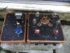
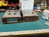
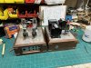
Update on the preamp project; I hade some 316 stainless pieces cut at the factory with our 4000W fiber optic laser. Sure beats the manual way. They fit the cabinets nicely.
upload_2023-3-3_19-13-41.jpeg
I did a dry fit with some of the components and everything lined up and fit right. I’ll polish up the stainless and start wiring this weekend.
upload_2023-3-3_19-16-1.jpeg
 
Was looking at your schematic again. You need to be aware of the max heater to cathode voltage for the 6J5 as a cathode follower. Per the RCA spec sheet it is plus or minus 90 volts. With 176 volts at the cathode the heater elevation circuit you have won't make the 90 requirement as it only elevates about 40volts. The formula for voltage dividers will will help you figure out the resistor ratio you need. Then with at least 86 volts elevation on the heaters the 76 near its limit of +/-90 VDC. The 6/12SN7 that was specified has a heater to cathode of +100/-200 VDC so the follower doesn't need as much plus elevation to stay in spec. You might be asking for problems with the 76 and 6J5 combo unless you can use separate filament supplies with different elevation voltages.
John
 
John, This is exactly the type of feedback I was hoping for. I knew I was wading closer to the deep end when I was veering from the original JE Labs schematic. I’ll study the data sheets to try to understand this better. I’ll most likely have more questions. Thank you - Jeff
 
There are plenty of good tube choices for a cathode follower. You could use a 6BL7 or 6BX7. They have cathode to heater max voltages the same as the 6SN7 and are higher power double triodes. Same pinout as an SN7. They could run at higher bias currents than the SN7 and give an even lower output impedance. Not too expensive at auction and for followers wouldn't have to be matched side to side so closely. There are many other triodes and pentodes that could be used either in pentode or in triode connection for a good follower.

You should get familiar with tube data sheets. They generally have max cathode to heater voltages specified along with lots of other useful info.
https://tubedata.edebris.com/index.html

John
 
John,
Thanks for the compliment. I'm more of a woodworker than an diy audio person. I'm confident with a saw but with electronics, it's been proven that I need to follow a recipe.

I spent some time reading and it definitely looks like you've saved me some time and heartache. I see exactly where I went wrong on this; I tried to save some money on the JE Labs design and use tubes less popular than the 6sn7. I've read that the 6J5 was the single triode equivalent of 6sn7 and following that logic the 12j5 would be the same but with 12v heaters at a fraction of the cost. http://vinylsavor.blogspot.com/2013/03/tube-of-month-6j5.html Maybe they're similar except for the heater to cathode max voltage. Thanks for the great advice to study the tube data sheets which I will heed from this point onward.

Since I've already invested in the stainless top chassis plates (not money but time and favors) I still want to use a quad of tubes. I've seen gobs of internet photos of people's JE Labs 6sn7/76 preamps and they all seem to have two 6SN7s, which I don't understand since they are twin triode. I thought about using the left side of one 6sn7 for channel 1 and the right side of another for channel 2. That way I could switch the tubes back and forth over time for longer life and even wear. Someone recommended against that but I can't remember why. Any suggestions that would preserve what I've already built and keep the schematic similar? Thanks, Jeff
 
Back
Top Bottom