• The move to the new server is done. There are some software and database maintenance updates in process. This has us passing the hat around to help out. We appreciate any donations. Seriously, even a dollar helps. The payment page may be found here - https://www.audiokarma.org/support.html

New Restoration Project: Pioneer ER-420

So exciting! I re-assembled the broken impedance switch and wired it back up. I used DeOxit D5 on all the front-panel switches; particularly the volume potentiometer. Tonight I did some simple measurements on the wiper, input, and loudness tap. The pot behaved pretty much as I expected with no power.

Moment of truth: I plugged the amp into my dim bulb tester, wired up speakers, and ran my PC audio through the AUX input on the amp. Turned it on, bulb went bright and then over 30 seconds or so dimmed to about 20% max. Front panel lights came on. Turned speaker switch on, input to AUX, mode to stereo and out came very clear audio! My volume worked smooth and well, but max volume wasn't very high -- likely dim bulb pulling it down. Played for about 10 minutes: Billie Holiday "Lady in Satin". So good. Powered it down and I'm going to bed.

I haven't replaced any capacitors, resistors, or any components. I have capacitors to replace all the oiled paper caps and the B+ filter caps. I guess I'll still do that.

It works!
 
Solid signs of life are a good thing. I tend to bring things up with as few component changes as I can get away with to verify basic functionality. Makes for easier troubleshooting later.
 
I haven't made much progress. I decided to start by swapping out the stock 2-wire cord with a grounded 3-wire cord. Pretty destructive process to get the strain relief out. Ended up cutting the cord in the process. Then I got a new strain relief that would fit the chassis hole, but the cord I got was too fat to fit. I'm going to need another cord.

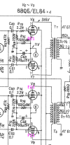
In the meantime I have cataloged and traced all the gray electrolytic and oil caps physically present and matched them up with them on the schematic I have. Everything was as speced from the service manual BOM. Except it looks like 2 caps were replaced with 1. In the attached schematic fragment, C53 and C54 (50uF 25V elyt) appear to be replaced by a single 60uF 125V elyt). There is a shared cathod-bias network between V1 pin 3 and pin 3 of V6/V7/V8/V9. This 60uF cap is in parallel with a 1kOhm SEF resistor tied to that network and chassis/ground. Does that sound reasonable that they would have made a schematic change to replace those two 50uF caps with a single 60uF cap without updating the service manual? How closely should I match this 60uF cap on replacement? I had ordered two 47uF caps to replace the 50uF that was on the schematic.

The power cord is the only thing destructive I've done so far besides repair the impedance switch. Anxious to get started with the soldering iron, but being abundantly cautious.
 

Attachments

  • Screenshot 2026-08-12 at 8.37.09 AM.png
    Screenshot 2026-08-12 at 8.37.09 AM.png
    240.5 KB · Views: 11
Often the service manuals aren't a perfect match for assorted reasons. If the part in the unit is original and the value doesn't match whats in the manual, go with whats in the unit. It worked with that part once, so it will work again with that value.

for the cathode cap though, I'd be fine subbing it with a single 100uF and calling it a day. The schematic shows a pair of 50 in parallel which is 100uF. Bit surprised they have two cap + resistor networks though. As-drawn it looks like per-channel stuff but if both cathodes tie together at point K, its electrically a single resistor + capacitor. Its generally cheaper to use 2 parts than 4.
 
A pair of strain relief pliers makes power cord replacement SO much easier. Here's an inexpensive set:

I use a Heyco plier which is really nice but somewhat expensive. I got so tired of trying to get strain relief bushing removed that I splurged on a good pair. A good tool sure is nice to use.

Good luck with your project.
John
 
Still not much progress. I ended up putting the old power cord back on because I couldn't get a 3-wire cord through the hole on the chassis and didn't feel comfortable reaming it out.

I had bought a cheap DMM that was super frustrating to use. It was trying to auto-sense what I was measuring and often got it wrong. I bought a Fluke 15B+ to replace it with. I then went through the schematic and noted every place where the voltage was called out and made a list of 35 different locations. Using my new Fluke, I was able to find 33 of the 34 locations physically on the amp and measure the voltages. With the dim bulb tester suppling about 70VAC, I was getting most unsurprising results. I think I have one bad tube or at least one where the cathode was reading dead zero volts instead of the 0.75V spec. I did not swap it out with a known good to see what's up yet. This was just to get a baseline measurement of the system before I really do anything destructive.

I guess my next step is to physically remove the power capacitors. Looking at the notes from AntiqueRadio.org Restuffing Electro, it looks like I'm supposed to use my dremel to cut these off. That leaves the pins soldered on the bottom side and I solder the new caps to the existing pins on the top side? Or try to remove the whole thing and solder the cap leads to the components underneath?

I'm anxious to get more free evenings to work on this. It takes me a long time to trace things out and reason what's happening physically and on the schematics and remembering/researching electronics.
 
Are these a clamp-in type? if so honestly I'd just get replacement clamp-in types. It will look nicer.

also I just hate re-stuffing caps. I find it to be a messy, time-consuming process and at some point I decided I just don't hate myself quite enough to want to deal with it.
 
yes, these are just clamped in. i've already bought the discrete replacement caps and didn't buy new cans. I'm not sure if I want to buy new caps to replace the replacements I have. I also don't think I want to re-stuff these cans. It seems shoddy, but I was thinking of just having the discrete caps just hanging out on top without the cans.

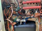
Looking more closely at this, when I unclamp them they will come all the way out. The terminals are part of the can. Seems like I have to desolder all the components and resolder them together with the new caps. Starting with these power supply caps seems more complicated than the other one-to-one replacements.
 

Attachments

  • IMG_2509.jpeg
    IMG_2509.jpeg
    102.2 KB · Views: 24
  • IMG_2510.jpeg
    IMG_2510.jpeg
    134.2 KB · Views: 23
Looking more closely at this, when I unclamp them they will come all the way out. The terminals are part of the can. Seems like I have to desolder all the components and resolder them together with the new caps. Starting with these power supply caps seems more complicated than the other one-to-one replacements.
Yes, use the schematic to be sure you are soldering the correct leads and grounding points. Checking the original wiring photos will help, too.

Good luck! :thumbsup:
 
Not sure what you meant when you said something about the new caps hanging out on top. I hope you didn't mean on top of the chassis. These caps will have very high DC volts across them. In the past, I have snipped the wires off the old can and used them for the new, under the chassis cap. If you leave the old (now disconnected) cap in place, it fills the hole and preserves the appearance. The factory grounding should be maintained for the replacements, or it can cause hum issues if it is moved. Following this, and wishing you success. Paul.
 
if you have the room they can go underneath, just mount a terminal strip so they aren't flapping in the breeze. Can recycle existing holes for this. Don't just float the caps in space though whatever you do.

two of those look like single section caps, so those are easy. The "complicated" one is 3 sections with a common ground. Not that big of a deal really, just tie all the grounds to a single terminal and run that to wherever the original cap grounded to.
 
"on top" i meant that the board has a little space underneath before the bottom plate of the chassis; maybe an inch. above the board is where all the tubes, transformers, and the power supply caps sit. those are what's pictured above: about 3 - 4". but there's a chassis cover that goes over those.

Wife is going out with friends tonight. I'll take appart one of the single section caps and learn what I see.
 
if you have the room they can go underneath, just mount a terminal strip so they aren't flapping in the breeze. Can recycle existing holes for this. Don't just float the caps in space though whatever you do.

two of those look like single section caps, so those are easy. The "complicated" one is 3 sections with a common ground. Not that big of a deal really, just tie all the grounds to a single terminal and run that to wherever the original cap grounded to.
c73f343c-43b5-4fe7-b4b0-c6bd0bd39a7e.jpg


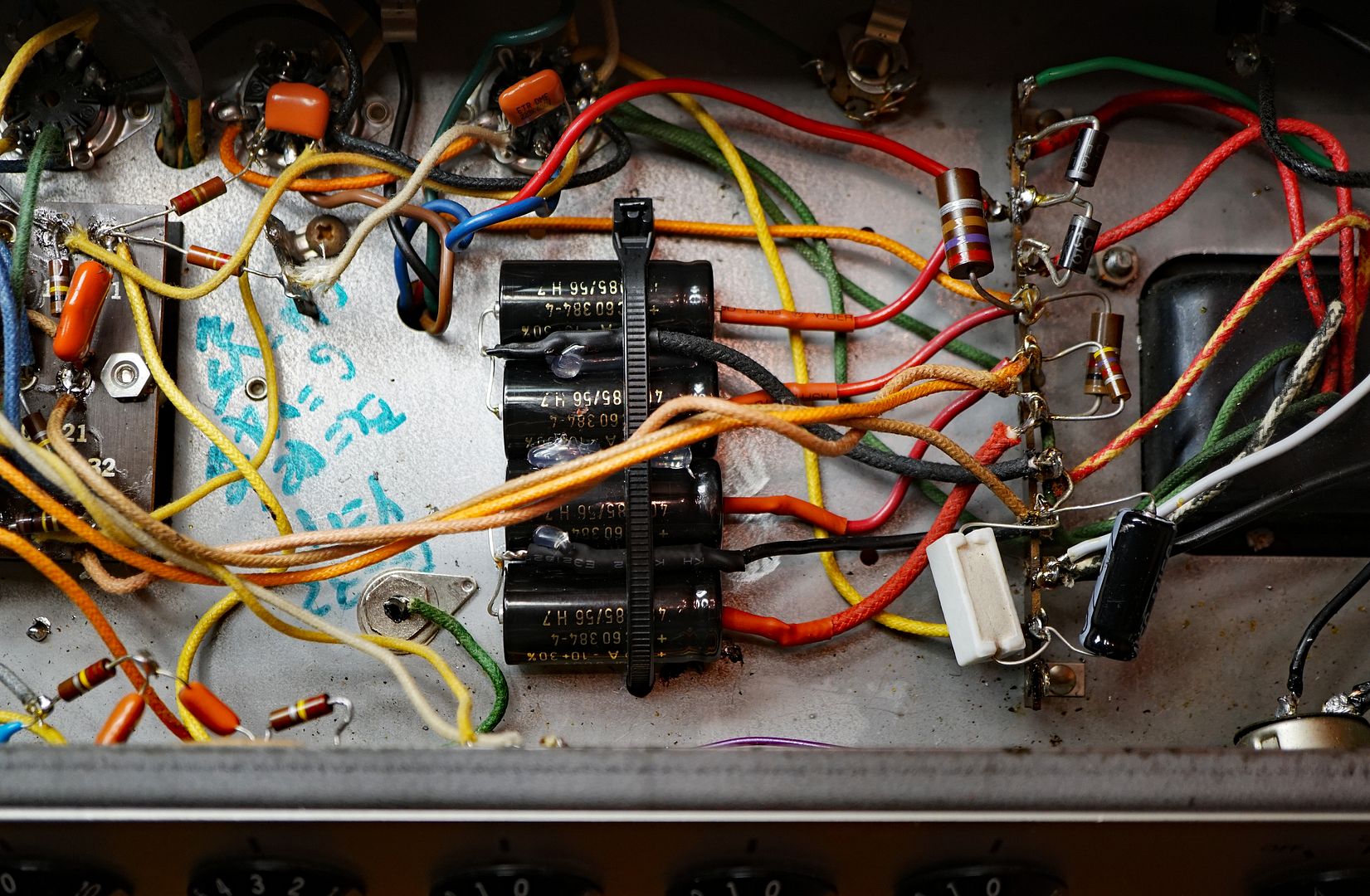
This is what I did (post #11). Four separate axial 20mfd/500mfd caps to replace a 20/20/20/20 at 450VDC cap can. After I removed the wires, I left the old can on the chassis (on top).

3M tie warp holders.jpg

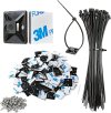
I used 3M tie wrap holders to hold the caps.
 
Last edited:
I've never had a lot of luck with those self-stick zip tie mount things. That adhesive just doesn't hold up very well.
The surface has to be free of oil and dust — and be dry. Then, put a tiny pea-sized amount of silicone sealer onto the pad.

It'll stay forever. Really.

If you are still worried, there are holes on the chassis for sheet metal screws.

:thumbsup:
 
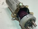
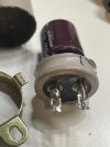
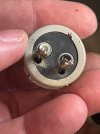
i got one of the simple single section caps off, and opened. pretty nasty inside. cleaned out ok. i drilled two holes through the bottom so i could run the leads from the new cap through and solder directly to the existing terminal leads on the bottom of the old can. i made sure that the negative terminal of the new cap is soldered to the black painted terminal on the bottom of the can. i also drilled a hole in the top of the can as a vent. i heard that these new caps will off-gas and need a vent. i don't know if that's true. i don't have any epoxy and i'm not sure about filling the can with epoxy around this new cap. what i'd like to do is just put the pieces back together and simply use the clamp to hold them together and then screw it down to the mainboard. what should i be doing here?
 

Attachments

  • IMG_2545.jpeg
    IMG_2545.jpeg
    70.8 KB · Views: 20
  • IMG_2544.jpeg
    IMG_2544.jpeg
    81.5 KB · Views: 22
  • IMG_2543.jpeg
    IMG_2543.jpeg
    85.9 KB · Views: 19
  • IMG_2536.jpeg
    IMG_2536.jpeg
    98.1 KB · Views: 18
  • IMG_2540.jpeg
    IMG_2540.jpeg
    63.3 KB · Views: 23
vent hole is fine, but it will only need that if the new cap explodes. The holes for the lead wires should be all you need here.

I wouldn't pack it with epoxy but thats me. Use whatever you like to stick the can back together and hide the sins with the clamp. Maybe a little superglue. If you want you can use some hot glue under the bottom of the new cap to help support it better.
 
Being impatient, I went for it. Took me a bit of fiddling, but got it installed lined up matching exactly as it was. Soldered a couple wires in and called it done! Powered up and measured voltages that looked good according to spec. Didn't burn house down. My first capacitor installed!!
 
if you have a tubing cutter that might do a slightly cleaner / straighter job of cutting the can.
 
Got my second single stage power supply capacitor replaced tonight. Same as the first, but 1/2 the time. Also, I'm really bad at desoldering.
 
Back
Top Bottom