• The move to the new server is done. There are some software and database maintenance updates in process. This has us passing the hat around to help out. We appreciate any donations. Seriously, even a dollar helps. The payment page may be found here - https://www.audiokarma.org/support.html

New Restoration Project: Pioneer ER-420

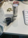
Any advice on how to tackle these multi-stage caps? I have 2 40uF,20uF,20uF 350V capacitor cans that I've previously ordered discrete 47uF and 22uF 450V capacitors to replace them. How do I ensure the right replacement cap is wired to the right terminal? Just go off the schematic and what components are tied to it?
 
On the side of the can, there should be 3 figures such as a triangle, circle and maybe a D or square. On the bottom of the cap, similar figures should be there. The can side should give the uf value for each figure. Match them up to the wire connected to the correct figure underneath. Verify where each wire goes with schematic that there was no mixup. Good luck. Keep asking questions. Paul.
 
The can should be marked with a shape or a number for the terminal. Old US caps were generally no marking, square, triangle, half-circle. I don't remember what Japanese ones were, other than negative is typically marked black.

zip tie or tape all of the parts that go to a specific terminal together to keep them grouped, and mark it with whatever symbol if you can.
 
Here's a 4 cap can I recently stuffed for a Scott amp,, I use super glue or contact cement for attaching the can,,1789158557363.png
 
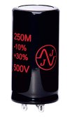
For the most part, if there's a clamp type electrolytic capacitor, I will buy another one that is similar. Here's an example. I have had good results with JJ Capacitors, they test very good and are reasonably priced.
 

Attachments

  • JJ Capacitor.jpg
    JJ Capacitor.jpg
    28.8 KB · Views: 5
Last edited:
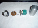
As for "FP" type or "Twist-Lock" style, I will often open them up too. I know that it takes a lot of time, but I prefer to uncrimp the capacitor, clean it out and put radial lead capacitors back inside. I test it before I re-crimp the bottom. It usually comes out well. But for more money, you can get these Twist-Lock style in many values.

CE Capacitor.jpg
 
The clamp-in types tend to be a fair bit cheaper than the twist-locks, and certainly easier to change. Don't have to melt the solder off the chassis that some lady with a soldering iron that looked more like a torture device installed 60 years ago.
 
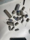
Wow! Marathon session today -- 8 hours of bench time. I replaced 19 capacitors and I think I'm done with all the electrolytics and oil-paper caps except two of the power supply multi-stage cans.

I got one of the cans removed, torn apart, and cleaned. But I'm having a hard time fitting my three discrete caps in the can. I may punt on that and go with something more like what you guys have suggested above. I wish I had just bought a replacement can, but I didn't and I'm not ordering one now that I am this close to done and already have the parts in hand. I'll figure it out tomorrow.
 

Attachments

  • IMG_2591.jpeg
    IMG_2591.jpeg
    77.7 KB · Views: 6
for multicaps, there is a tall skinny cap that fits better for restuffing purposes. Forget the series but they are like 10mm diameter and double the length of a typical cap in the same value.
 
The surface has to be free of oil and dust — and be dry. Then, put a tiny pea-sized amount of silicone sealer onto the pad.

It'll stay forever. Really.

If you are still worried, there are holes on the chassis for sheet metal screws.

:thumbsup:
Junk, they look good for a while but are guaranteed to fall off over time. If you use an adhesive remove the double-sided tape completely as using a silicone adhesive on one side the tape will end up coming off the other side, the side stuck to the plastic holder. Use the small holes there to fasten it with and use some small rivets. If you want to use good adhesive cable tie holders and adhesives I recommend using click bond products, the only downside is they are expensive.
 
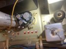
I don't know if this is good enough, but here's what I did for one of them: used the bottom of the can that i cut off, drilled holes through the base near the solder leads, and pulled the leads from the new caps through. wrapped some electrical tape around the perimeter of all the leads so they wouldn't be outside touchable and then clamped it into place with the existing clamp. I don't know if this qualifies as "flapping in the breeze".
 

Attachments

  • IMG_2600.jpeg
    IMG_2600.jpeg
    87.5 KB · Views: 7
  • IMG_2598.jpeg
    IMG_2598.jpeg
    71.4 KB · Views: 7
"flapping in the breeze" is no mechanical support... if its secure to the chassis and suits ya,,, it should work,,,
 
Functionally its fine, just not the best looking. I have run extensions on the cap legs to put one center above the others if that's enough to get it stuffed inside the can before. Usually need to use some glue for mechanical support

I've also made the can have less sections and mounted a cap underneath. In some cases even just attached to the original terminals below deck.
 
yea, i could definitely fit two of the caps back in the can. for this one, there's room below deck for the third to hang right off the original terminals. My last remaining can does not have any extra space anywhere close. Even stacking, these won't fit in the can. It's not the best looking for sure. If it had it to do over, I'd order something like kvflyer recommended above. Maybe if I decide to sell this unit, I'll replace these caps with something that looks nicer.
 
All electrylitic and oil/paper caps have been replaced. With the dim bulb I was checking all the called out voltages from the schematic and noticed quite a few cold solder joints. Powered back down and refilled them as best I could. Brought it up to full power and did a voltage measurement across the board. The 100W bulb was limiting too much and some of the tubes weren't reaching operating temp. With full power, I got almost all the spec voltages within about 10%. There's one that's very high, but everything else around it is within 10% of spec.

Plugged in some equally old speakers that also probably need to be recapped. Tested FM, AM, Aux, and Tape Mon. All played sound. AM and FM were pretty noisy. No FM antenna had something to do with it. Not sure how much I care about radio right now. Tap mon works pretty nice. Aux also works pretty well. Both have a hiss that varies in intensity. Tap Mon seems less than Aux. Loudness, balance, bass, treble, high filter and low filter all modified the sound output. Hard to tell how well loudness and the filters worked.

Not quite sure how to chase down the hiss. I've used Deoxit on the switches, but could probably do it again.

Did a tap test with no music and volume turned way up. V1 magnified my taps. V3 definitely rang like a bell. V3 is a 12AX7. V1 and V2 are also 12AX7s and are the first input amp, one for left and one for right. They both feed into V3 right after the volume control and before the final gain stages.

I'm literally scared I'm going to have to chase down all the composite resistors in the signal path and replace those. I naively thought I could replace all the caps and I would be done and this amp would sound great. I'm realizing I probably still have a lot of work to do.
 
Last edited:
could be noisy tubes, could be noisy resistors, could just be a noisy circuit. Quick and dirty troubleshooting would just be to pull the first tube signal gets to and see if it stops the noise. If not, move to the next, so on and so forth. When you pull a tube and it goes away completely, the problem will generally be at or immediately upstream of that stage.
 
could be noisy tubes, could be noisy resistors, could just be a noisy circuit. Quick and dirty troubleshooting would just be to pull the first tube signal gets to and see if it stops the noise. If not, move to the next, so on and so forth. When you pull a tube and it goes away completely, the problem will generally be at or immediately upstream of that stage.

I'm not sure what you mean by "pull a tube". Do you mean swap the tube with a new one? Can you run the amp without the tube in the socket?
 
Remove the tube from the socket. It will run with tubes missing but won't pass signal.

Looks like V1 and V2 are phono / tape head
V3 is the tone control amp
V4 and V5 are the phase inverter / voltage amp in each channel.

I might pull V3 and see if it shuts up. If it does, try swapping it with another 12ax7, maybe one of the phono tubes. if no change, check the plate resistors on v3. Cathode is bypassed so that really can't be noisy, and the stuff in the tone control doesn't carry current so they generally won't contribute to noise either.

If V3 doesn't take care of the noise, likely V4 / V5 or something around them depending which side its on.

Don't pull the EL84 tubes, each channel needs both installed to bias correctly.
 
Ha! You're revealing that I don't actually understand how tube amps work. I'm just trying to check my understanding of what you've said:

Pulling at tube will kill the signal, but there might still be audible hum/hiss/squeal in the background. If so, that noise is being generated or injected after the pulled tube. The inverse is also true, if pulling a tube results in total silence the noise is at or before that pulled tube, not after it.

So pulling each tube, one by one, will isolate where the noise is coming from even though the amp largely won't pass signal with any of them removed.

V3 is the likely culprit. I did order a JJ ECC803s / Hi-Performance 12AX7 Preamp for $33 delivered. I worked a marathon session on it this weekend and ignored other chores. I likely won't get to this again until the new tube arrives.

Thanks for all the advice!
 
yep, its just low-effort stage isolation. Not a complete answer but it will at least narrow down the area of concern rather than having to look at every single thing.
 
Back
Top Bottom