• The move to the new server is done. There are some software and database maintenance updates in process. This has us passing the hat around to help out. We appreciate any donations. Seriously, even a dollar helps. The payment page may be found here - https://www.audiokarma.org/support.html

New sx-636 Refurb Issues and Questions

fromnowon

AK Subscriber
Subscriber
Hello, Pioneer Forum.

I think I'll start a fresh SX-636 thread, if that's ok.

(I had a really great success recapping an SX-434 this summer, thanks to help from you guys on this forum. I still can't believe how great it turned out. I gave it to my son after enjoying it for a few months. It was a blast. You guys are awesome. I learned a lot from that too.)

Next I'm going to try to fix up an SX-636, and of course there are MANY threads which I've been referencing, but I decided to start a new thread because I'm sure I'll run into new issues, I always seem to.

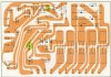
Today I started studying the Power Supply board. I noticed there's a typo on the power supply schematic, two C7 caps, one electrolytic and one ceramic. I think? That's strange. No big deal just interesting, haven't seen that mentioned in the other SX 636 threads so I thought it was worth posting. I'll leave the ceramic disk C7 and replace the electrolytic C7.

Also on my SX-636, there doesn't seem to be enough slack on the wires to flip the PS board in place and get to the back. I got it off the plastic posts and loosened the wires as much as I could, clipped a zip tie - everything, and there just isn't enough length without really yanking on wires. So I guess I'm faced with de-soldering the posts or unwrapping wires which I hate to do but oh well. I see that two of the wires are already soldered on my PS board's posts for some reason so maybe someone cut them and now they are too short. Not sure what would make someone cut two of those wires and leave the others.
Capture.JPG
 
Register to hide this ad
Nice catch!
FWIW, That is the pcb foil side layout, not the schematic, and in my service manual it is mislabeled on both the AWR-060 (FV, KCU) and the AWR-061 (GN) layouts. However in the actual schematic the 100pf cap near Q2 (B-C) is labeled C10.
Yes, I know I am being pedantic, please forgive me . . .
 
Last edited:
Two months later . . . I finally got some time.
If anyone is interested! ha ha
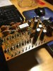
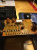
I ended up taking out the AWR-060 Power Supply board. There was just no way I could figure out how to get to the back of it without doing so. (I unwrapped the wires - shouldn't have done that, I knew better, should have unsoldered the pins. Oh well.) Must be standard procedure on SX-636's to remove that board to replace parts?
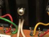
Anyway I got the wires all soldered back on correctly and with solid connections. There is practically no extra wire at all.
Maybe tomorrow I can check my voltages and fire it up on a dim bulb tester.
Having the board out did make it easy to clean up and replace transistors, caps and diodes.
IMG_1423.JPG

IMG_1426.JPG
 
I’ve done a few 636s and didn’t have to desolder pins or anything. I think you can loosen the wires underneath and get enough slack to tilt the board more.
 
It's generally preferred to De-Solder the posts from the board, although there are pins on some boards that have had the end swaged and soldered, therefore are harder to remove, so be careful. I've done practically every unit in the x3x series and haven't had to remove or unwrap a post yet. You will have to loosen up a lot of tie wraps on the harnesses to get a bit of slack, but it's do-able.

Solid core wire is brittle compared to stranded, so it tends to break easier. if someone was poking around inside, wire's can and do break, usually at the post where they are under the most strain. The #5 wire on my SX-939 protection board would break at the pin, just by looking at it when I was doing that overhaul. Ended up removing it totally and replacing it with a new run 20ga solid core in the same cover color. Voila! No more problems.
 
Thanks, I really appreciate the comments. You guys are pro's! It's great to be able to get advice and it's so easy to mess up.
I think I'll tackle AWH-034 Power Amp next.
I'd love to remove the heat sink to clean it. I wonder if it's safe to leave the D5/D6 STV3H diodes hanging on their soldered leads and just unscrew them, if I'm careful. Or is it better to not touch them? Wondering what you guys would do on that.

IMG_1427.JPG
 
Well, one more question I have please, if you guys have time!

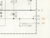
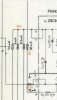
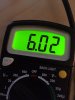
I checked the PS board voltages. They are great except I'm getting 13vDC at pin 14, and per schematic I think it says should be 6v.

I see that Pin 14 is the salmon-colored wire that feeds the lamps. Even at the lamp housing it is 13v.

I tested R9 and it was 268 ohms, just tested in-circuit quickly, and it looks fine visually too. Is R9 supposed to knock that voltage down to 6v?

The lamps seem to work fine.

Here's another thing - I have another SX-636 here (it was cheap, a channel is out!) and pin 14 is also 13vDC on it. Maybe I don't understand the schematic.

If pin 14 really should be 6v, and R9 is ok, what else could get it there? Maybe it's not good to be sending 13v to the lamps.

This must be an application for Ohm's law, I have a feeling . . .


pin 13 and 14 PS voltages.JPG

pin 13 and 14 big schematic.JPG
 
Depends on what you want to do on the AWH-034 Power Amp and how long the STV3H will hang free. The leads can break very easy and you will have a hard time to find new STV3H or some used ones in good condition.
I had the same problem on my SX-750 with a very long delivery time for some parts. So just to be save, I unsoldered both STV4H and stored them at a save place until everything is reassembled again.
 
Pin 14 goes to the stereo indicator lamp. Check if you have the stereo lamp on. With the stereo lamp ON you should have the 6vdc. As long as the stereo lamp is OFF the voltage will be higher and I think, that it can go up to the 13 vdc what you measure now.
 
It’s a pleasure to help here at AK. I had the same problem on my SX-737 and it took me quite a while and some reading across the forum, to figure out the connection.
 
it's great! I hope I can help some others some day on this forum to repay how nice people have been to me. It's amazing to be 'connected' with someone in Germany who likes this stuff too, it blows my mind what's possible these days.

I just noticed my two SX-636's have different styles of STV3H diodes. Interesting. Maybe they are just
mounted differently. I'd think the one on the left would stress the leads more.
compare STVH.JPG
 
I believe it’s less stress if the mounting position is from top, like on the left picture with the longer leads. On both of my SX-737 it has the same position. If you unsolder them you must be sure with the cathode and anode side.
 
Hello, here is an update.

AWH-034
I replaced 10 transistors and 6 caps, and the output transistors and new mica and compound. Also replaced the little trimmers. No issues at all, I just went slow and triple-checked pinouts and polarity. Decided to just clean the heat sink while it's bolted in the frame, in order to not disturb the STV3Hs. I was able to loosen the wires and lift the Power Amp board enough to get a screwdriver on the output transistor screws.

I noticed that there are jumpers on this board (9 to 22, and 12 to 18). These seem to tie together the collectors of the output transistors. They aren't on the schematic, not that I can tell anyway.

Anyway now I have all the caps/transistors done on the Power Supply board and the Power Amp board. Listening now, with headphones for a few hours (probably shouldn't!) - wow, it sounds awesome! I know it sounds better than before I started.

The only issue is some faint, random/sporadic fuzzy static in between songs, or when I turn down the volume all the way (I'm using AUX). It comes and goes, very quiet. I hope replacing caps / transistors on the tone amp and eq amp boards will get it. I've also not cleaned the pots and controls and switches yet so maybe that's the cause.

I really like this receiver. Got it for $20 "parts not working" at a flea market sale last summer.
 
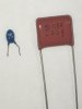
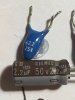
Looks like for C5 and C6 on AWK 035 my mission is to replace that tiny tantalum 1uF 25V cap on the left with the new much larger metallized (?) film capacitor on the right.

Can anyone confirm that the new film cap is not polarized (doesn't matter which way I install it?).

I guess I'll have to do some lead bending and maybe should try to add insulation to the leads too.

Thanks

IMG_1504.JPG
 
Yeah, Wima film is what you want to use there. I don't use the big Panasonic stuff on pretty much anything except Marantz gear, where they're replacing other big film caps.
 
Back
Top Bottom