

You are using an out of date browser. It may not display this or other websites correctly.
You should upgrade or use an alternative browser.
You should upgrade or use an alternative browser.
New sx-636 Refurb Issues and Questions
- Thread starter fromnowon
- Start date

Oldsansui441
Super Member
Good call by pa_200, any of those pushbutton switches in the circuit can be suspect even though l think you said you have cleaned them already, they may need another. Maybe it was just coincidental that the problem arose after you replaced the components on the AWK-035.

Thanks again, I really appreciate you guys. Here's what I had time to check so far today. My goal is to get this working before the end of the year 
(I also want to check the voltages at each leg of Q3 and Q5; haven't done that yet.)
There are a lot of components in a pretty tight area right there:
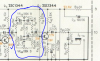
- First I checked for signal at R13 right where it feeds C5 (neg). Really good strong signal there. Volume and balance affected it. I guess the volume control is ok on Left channel so that's good news.
- Then I checked the emitter leg of Q1. I was able to get a signal there too, and it is affected by volume.
- Same at Q3: I can get a signal at the emitter and it's definitely affected by volume.
- Then I checked Q5 emitter. No signal there at all. I think there should be.
(I also want to check the voltages at each leg of Q3 and Q5; haven't done that yet.)
There are a lot of components in a pretty tight area right there:
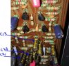


Tip - look at the signal on BOTH leads of C13, C21, C23.
C13 is the input to the tone network,
C21 is the sensing input for the tone network output (the base of Q5 stage)
C23 is the feedback signal that samples the Q5 output (the collector of Q5 stage) and goes back to the network.
R29, VR3(100k) R35 R33 C15 & C17 bass boost or cut network
R31 VR4(100K) R37 C19 treble boost or cut network
Centered pot wipers are the neutral configuration.
I'm NOT sure how much signal loss is engineered (expected) into those tone networks between stage Q3, and the feedback enabled Q5 stage.
C13 is the input to the tone network,
C21 is the sensing input for the tone network output (the base of Q5 stage)
C23 is the feedback signal that samples the Q5 output (the collector of Q5 stage) and goes back to the network.
R29, VR3(100k) R35 R33 C15 & C17 bass boost or cut network
R31 VR4(100K) R37 C19 treble boost or cut network
Centered pot wipers are the neutral configuration.
I'm NOT sure how much signal loss is engineered (expected) into those tone networks between stage Q3, and the feedback enabled Q5 stage.
thank you Mark, I appreciate your comments.
Here's a partial report:
- BTW, still getting a signal at emitter of Q3, can see it with scope on 10 mV per DIV
- C13: both + and - legs show a good signal, can see it at .5V per DIV. Looks good.
- C21: - leg shows a signal a 5mV setting and tone controls make it move a little. I'm not sure I see a signal at all on the + leg of C21, can't get a sine wave that's for sure. Since R33 feeds C21, maybe it's suspect?
- C23: I'm able to see good signals on both legs.
I'm thinking of removing R41, R39, R29, R33, R35, R31 and R37 so I can test them properly or just replace them.
Is it possible there's a bad resistor in that path? Visually they look good.
Is that a reasonable next course of action, as I can't really test them in circuit, I don't think.
Thanks again.
Here's a partial report:
- BTW, still getting a signal at emitter of Q3, can see it with scope on 10 mV per DIV
- C13: both + and - legs show a good signal, can see it at .5V per DIV. Looks good.
- C21: - leg shows a signal a 5mV setting and tone controls make it move a little. I'm not sure I see a signal at all on the + leg of C21, can't get a sine wave that's for sure. Since R33 feeds C21, maybe it's suspect?
- C23: I'm able to see good signals on both legs.
I'm thinking of removing R41, R39, R29, R33, R35, R31 and R37 so I can test them properly or just replace them.
Is it possible there's a bad resistor in that path? Visually they look good.
Is that a reasonable next course of action, as I can't really test them in circuit, I don't think.
Thanks again.
Oldsansui441
Super Member
s that a reasonable next course of action, as I can't really test them in circuit, I don't think.
Thanks again.
Hi, you can test some in circuit. If they test different in circuit to their given specs then you can desolder one leg and re test. You can also compare them to the good channel if this helps.
Those two networks I NAMED, think of them as INDEPENDENT, both contributing HALF of the signal, divided by frequency band. Bass and Treble.
You have the right idea about posting pictures, show the foil side, and a topside where Q5 can be seen - I see a corner of Q6 and as far as I can tell, that one went in correctly.
SEEING GOOD SIGNALS on BOTH sides of C23 means Q5 is working!!!!
Check the signals at C25 !!!! BOTH sides!!! Compare the signals to the corresponding point on the working channel. C25 minus side has a LOT of exposure to ground traces!!! Slobber bridge?
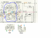
You have the right idea about posting pictures, show the foil side, and a topside where Q5 can be seen - I see a corner of Q6 and as far as I can tell, that one went in correctly.
- C23: I'm able to see good signals on both legs.
SEEING GOOD SIGNALS on BOTH sides of C23 means Q5 is working!!!!
Check the signals at C25 !!!! BOTH sides!!! Compare the signals to the corresponding point on the working channel. C25 minus side has a LOT of exposure to ground traces!!! Slobber bridge?
Last edited:
Hello again, thanks for your patience!!
This has been interesting.
I went ahead and pulled and replaced the 7 resistors, figuring I could clean up and double check and it wouldn't hurt. That didn't get left channel to work though and all the resistors tested perfect (I figured). Waste of time.
I think I'm going to try comparing channels more, and maybe make a splitter for my signal so I can feed the same signal to L and R (without having to unplug/plug each time).
Most interesting thing I've found:
On c14 I get a strong signal, both legs. of course, that channel sounds good.
on C13 i get a comparatively wimpy signal or maybe even no signal at all.
However I do see a good sine wave signal from Q3's Emitter.
I think I have a problem around C13. Something besides Q3 is affecting it, I think.
Here are some top side pictures (easy to tell the new resistors).


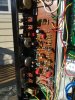

There are some challenges on the back, here is the worst, and what I did with it - it's at the Q5 collector and one of the leads for the left channel 2.2 uF cap:
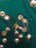

not very pretty but there is continuity across that ugly slobber blob, still it's not great
Few more of the back:
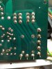
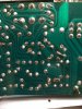
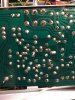
This has been interesting.
I went ahead and pulled and replaced the 7 resistors, figuring I could clean up and double check and it wouldn't hurt. That didn't get left channel to work though and all the resistors tested perfect (I figured). Waste of time.
I think I'm going to try comparing channels more, and maybe make a splitter for my signal so I can feed the same signal to L and R (without having to unplug/plug each time).
Most interesting thing I've found:
On c14 I get a strong signal, both legs.
of course, that channel sounds good.on C13 i get a comparatively wimpy signal or maybe even no signal at all.
However I do see a good sine wave signal from Q3's Emitter.
I think I have a problem around C13. Something besides Q3 is affecting it, I think.
Here are some top side pictures (easy to tell the new resistors).
There are some challenges on the back, here is the worst, and what I did with it - it's at the Q5 collector and one of the leads for the left channel 2.2 uF cap:
not very pretty but there is continuity across that ugly slobber blob, still it's not great
Few more of the back:
Put the front panel mode switch to "MONO" from "STEREO", then both channels will be the same, while the balance control will still function.
Put the front panel mode switch to "MONO" from "STEREO", then both channels will be the same, while the balance control will still function.
Oh! MONO will send a signal input to AUX Left channel ONLY to both Left and Right sides then, so I can compare?
If you look on page 9/10 of the sm you will find in the middle s6=mode switch. On the block diagram the switch is shown open which means, the unit runs in stereo. With the advice from markthefixer you push the bottom, the unit runs in mono and the signal should be the same for left and right.
very useful, thank you. I see - Stereo mode sends signal from 21 all the way down to 10 (and from 23 to 11). Mono mode sends the signal from either 21 or 23 down both sides. It's a high-level view of what I've been trying to trace. I think the Pioneer SM is really excellent.
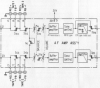
Thanks for all the help the last few days. I'm not giving up, but have to go back to work tomorrow. It's been great to learn how to trace a signal; that's where I'll pick back up, comparing signals down both sides. Now that I know how to do it I can check more effectively against the working right channel.
Thanks again.
I hope this will help some other SX-636 projects out there.
Thanks again.
I hope this will help some other SX-636 projects out there.