
• The move to the new server is done. There are some software and database maintenance updates in process. This has us passing the hat around to help out. We appreciate any donations. Seriously, even a dollar helps. The payment page may be found here - https://www.audiokarma.org/support.html

New sx-636 Refurb Issues and Questions

Sure, they are these:
647-LKG1J682MESCBK
at Mouser

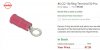
The terminals are snap-in style which I guess you could solder wires to but I found some ring terminals and just cut off the plastic, and they seem to fit well and are very easy to solder on the lugs. I used these:
ring term.JPG

That's a great point about the connections - they are not intuitive. I'll probably label the old wires to make sure I don't lose track and of course, take pictures. I'll be careful to discharge the old ones for sure! I appreciate the warnings so I can prevent any mistakes.
 
I put in the new Nichicon filter caps today, it was easy.
There is noticeably less background "hiss" now - almost none, and I think the bass might be somewhat more "punchy" and tight. Sounds really great.
The clamps fit perfectly. These caps seem to be a really good choice. (Thanks Avionic). Maybe I should have painted the clamps . . . I did clean them.
IMG_1606.JPG
 
old caps were -20% +80% spec
thus 6800 is 5440 to 12,240 new. back then.

did you do that with the NEW ones before you installed them?
 
No, I had the idea but forgot to test the new ones before I installed them, that would have been interesting. The new caps might be just as far off 6800!! I see the new ones are 20% tolerance also. The new ones sure seem to sound better, to me anyway.

I love this SX-636 so far, really like listening to it. Thanks very much for the comments and help! I'm about to have a couple of questions - have to get organized first.
 
One small clarification I wanted to get into this thread.

above in post 16 we were discussing AWK-035, C5 and C6 which originally are tiny blue 1uF tantalums.

Films are non-polar.. Why did you get a 250v to replace a 25v? Lead spacing is to wide. [URL='https://www.mouser.com/ProductDetail/WIMA/MKS02-1-50-10?qs=sGAEpiMZZMv1cc3ydrPrF9SBthQCDPcrcckziR3XnN8%3D' said:

  • Actually, I found that 505-MKS02-1/50/10 2.5mm lead spacing seemed too narrow .
  • I used these: 505-MKS21.0/63/5 (I think, I already had some so didn't order them). These have 5mm lead spacing and they fit perfectly in those spots.
 
Hello, I have another question, please.

Working on the Power Amplifier adjustment. The lowest I can get for Left Channel (21 & 17) is 42.0 mV. The lowest I can get for Right Channel (8 & 11) is 31.7 mV. That's all the way CCW. I decided to increase the Right Channel to 42 mV so they match.

Of course, the goal is 20 mV! So I'm twice that high.

This is with all the caps and transistors replaced.
Also,
- Been running the amp for a few hours today - btw, it sounds great! I love this receiver. Anyway, it's warmed up for sure.
- I connected dummy loads to L and R, A terminals. 8 ohms.
- Nothing plugged in AUX.
- Tone flat, Loudness off, Volume all the way left, balance centered.

Also, I replaced the trimmers with Bourns 652-3362p-1-101LF, 100 ohm, same resistance as original VR1 and VR2,
https://www.mouser.com/ProductDetail/Bourns/3362P-1-101LF?qs=me8TqzrmIYW7oAkP8ZuVYw==
That was pretty straight-forward I thought, with the screening on the board. They seem to work well and are very smooth/precise.

Thanks for any advice.
 
Should I try a 200 ohm trimpot, to add more resistance in the circuit, to enable 20 mV?
Like these?
https://www.mouser.com/ProductDetai...=sGAEpiMZZMvygUB3GLcD7uBcHvh8FSVun6ip4y0mgtU=

Is it possible that the new transistors I subbed in, which were the regular recommended ones on here, necessitates this? I wonder if you guys who restore sx-636s have run into this issue where 100 ohm trimpots aren't enough.

I wonder how this adjustment arriving at 20mV affects the sound or reliability of my amp . . .

I suppose I should check DC offset too.

Anyway thanks very much for any guidance!
 
Sorry I can't give you an advice on this one. Would like to learn the fix as well. Hope for a replay from Merlyn or MTF.
 
Thanks again, from what I've been reading, it seems important to arrive at value closer to 20mV on the adjustment. I don't think I should leave it at 40 mV. Still wondering if higher resistance trimpots would get me there as 100 ohm pots aren't working after my restoration (which included new output transistors).

Thanks for any input!
 
Hi, yes don't run it with the bias at 40mV. You can go up to a 200 ohm pot no problem if you have ascertained that in this particular circuit higher resistance equals lower bias current. You can check the resistance across your trim pots in their current positions to confirm this (two of the three pot pins will likely be tied together via the circuit), make sure to discharge your main filter caps first before getting back in there.
 
Thanks!

if you have ascertained that in this particular circuit higher resistance equals lower bias current

Well, I'm not sure, looking for an opinion - I was reasoning that since 100 ohm pots (same as original stock values) all the way CCW results in the current being too high, maybe a VR that ranges to more resistance would be a solution.

Or maybe replacing the parallel resistors R21 (and R22) with a higher value than the current 220 ohms ones would be an alternative? (that way I wouldn't have to order new trimpots; i have a kit of resistors, so would be easier)

Thanks for the reminder to discharge the filter caps!
Capture2.JPG
 
Did you MATCH Q1 & Q2 for hFe? These two are the input differential pair and if not matched your idle offset will NOT come down to spec. In this case with 2SA763's it adviseable to replace if you have a higher idle offset that is NOT adjustable to spec.
 
all the way CCW results in the current being too high, maybe a VR that ranges to more resistance would be a solution

You're welcome. As l mentioned earlier, you will have to measure them as they are now to determine whether you are at max resistance (100 ohms) or close to 0 ohms. You see depending on which two legs are tied together on a three pin pot determines whether CCW means less resistance or more. Hope this makes sense.

You are correct, once you have the above information you could use a different value at R21 (22) as this resistor is in parallel.
 
Last edited:
Did you MATCH Q1 & Q2 for hFe? These two are the input differential pair and if not matched your idle offset will NOT come down to spec. In this case with 2SA763's it adviseable to replace if you have a higher idle offset that is NOT adjustable to spec.

Hi Larry, fromnowon hasn't got to the DC offset yet (l don't think) but a good idea for sure after this bias issue gets squared away.
 
As the current through the bias servo circuit (D3, D5, R21 and VR1) is increased, the bias current through the output transistors decreases and vice versa. That’s why it’s very bad to have an STV varistor lead break while powered since it causes the bias to go to maximum which can destroy the output transistors unless a fuse blows first. So in order to decrease the bias current, you need to reduce the resistance of the trimmer. Unfortunately, you can’t reduce the resistance to less than zero ohms. Increasing the maximum resistance of the trimmer will only allow you to increase the bias further than you can with the 100 ohm trimmer. So, you would only want to do that if the bias was too low.
 
Thanks LesE for that explanation, how about trying a 100-150 ohm resistor at R21? I haven't personally had an issue with the bias being out of range on any of the SX series. Out of curiosity which transistor subs did you use for the main amp fromnowon?
 
Thanks LesE for that explanation, how about trying a 100-150 ohm resistor at R21? I haven't personally had an issue with the bias being out of range on any of the SX series. Out of curiosity which transistor subs did you use for the main amp fromnowon?

Once the trimmer is set to 0 ohms, R21 which is in parallel with the trimmer, does not have any affect on the combined resistance. At 0 ohms, the trimmer is effectively shorting R21. R21 serves as a fail safe in case the trimmer goes intermittent or open which again could potentially kill the outputs.

Judging by the photos that the OP posted earlier, it looks like the drivers were replaced with TO-126 devices - possibly KSC2690/KSA1220. If so, these are appropriate replacements for this application.

One thing that I'd look at is the voltage drop across D3. The larger the voltage drop, the greater the bias will be. A possible solution might be to replace it with a Schottky diode which will have a lower forward voltage. If D3 is bypassed, the bias should drop to 0 but it may be difficult to get to 20 mV. I'd also look R17 and R19 which have a direct affect on bias.
 
Last edited:
Once the trimmer is set to 0 ohms, R21 which is in parallel with the trimmer, does not have any affect on the combined resistance. At 0 ohms, the trimmer is effectively shorting R21. R21 serves as a fail safe in case the trimmer goes intermittent or open which again could potentially kill the outputs.

Of course, l knew the path of least resistance, might have needed more sleep last night, haha :D. Yes those drivers should be fine, just trying to ascertain what might be causing this issue on this particular unit.
 
Just speculating but when replacing drivers and/or outputs, small differences between Vbe specs can result in significant changes in bias current. Most of the time, this is easily compensated by the bias trimmer. It may be possible that in this instance, the difference may have been enough to move the bias outside the range of the trimmer. If this is the case, then working with the voltage drop across D3 may be an acceptable way to address the issue.
 
Back
Top Bottom