• The move to the new server is done. There are some software and database maintenance updates in process. This has us passing the hat around to help out. We appreciate any donations. Seriously, even a dollar helps. The payment page may be found here - https://www.audiokarma.org/support.html

New sx-636 Refurb Issues and Questions

Thanks for the replies and great info, I really appreciate it
I'll check some things as soon as I can and report back!
Did you MATCH Q1 & Q2 for hFe? These two are the input differential pair and if not matched your idle offset will NOT come down to spec. In this case with 2SA763's it adviseable to replace if you have a higher idle offset that is NOT adjustable to spec.
Yes, I believe so as I had read that it's important, I'll check my notes and maybe pull them to be sure!
 
Thanks !!
Been out of town this week - so haven’t been able to look,
Will check DC offset!
Also I remember when I picked the transistors out of the lot I received, hfe varied quite a bit between them.
I picked and installed the highest hfes I could match up.
I could try some of the transistors with lower hfe’s . . .
 
Also I remember when I picked the transistors out of the lot I received, hfe varied quite a bit between them.
I picked and installed the highest hfes I could match up.

Sounds like you did a good job there :thumbsup:. The DC offset should be as close to zero as possible, this will not have any effect on the bias though.
 
Did you MATCH Q1 & Q2 for hFe? These two are the input differential pair and if not matched your idle offset will NOT come down to spec. In this case with 2SA763's it adviseable to replace if you have a higher idle offset that is NOT adjustable to spec.

On AWH-034, I replaced Q1-4 with matched KSA992FBU's. (Originally my amp had 2SA763's).
I measured the original 2SA763s when I removed them and they ranged between 311 and 397 hfe values.

hfe's for the KSA992 batch I got from Mouser seem to fall in 3 groups of about 438, 419 and 397

I'll bet what I used in there now are the 438 hfe's which seems considerably more than the original 2sa763's hfe ranges.

Maybe I should replace Q1-4 with the 397 hfe KSA992s, double check matching, and try those in Q1-4, and see if it lets me arrive at 20mV, would that be worth the trouble before trying other solutions?

Thanks again for helping me sort this out!
 
Judging by the photos that the OP posted earlier, it looks like the drivers were replaced with TO-126 devices - possibly KSC2690/KSA1220. If so, these are appropriate replacements for this application.

Yes, I used 512-KSC2690AYS in Q7 and Q8, to replace the 2sc1509s. Thanks!
 
.... The lowest I can get for Left Channel (21 & 17) is 42.0 mV. The lowest I can get for Right Channel (8 & 11) is 31.7 mV. That's all the way CCW. I decided to increase the Right Channel to 42 mV so they match.
......
Also, I replaced the trimmers with Bourns 652-3362p-1-101LF, 100 ohm, same resistance as original VR1 and VR2,
https://www.mouser.com/ProductDetail/Bourns/3362P-1-101LF?qs=me8TqzrmIYW7oAkP8ZuVYw==
Just another strange idea came up, reading your last few posts. Have you got one spare trim pot from the used Bourns 652-3362p-1-101LF?
If so, I would measure the resistance with the trimmer turned fully clockwise. It should be close to zero. And second the value between the left and right leg should be close to 100 ohm.
 
Actually, I was playing with the new pots before I installed them and did just that! I do remember getting 100 ohms one way and zero the other way. I don't have any extras but I could sure pull one out and check it.

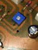
Just to double-check orientation, I'll attach a few pictures of one of them. I think they are installed correctly.

From bourns data sheet:
From Bourns Data Sheet.JPG

So that leg that's sticking out to the bottom left is the wiper, terminal #2 (this is VR2 near pins 10 and 11):
IMG_1660.JPG

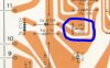
From the service manual, the wiper is on the big trace, on the side opposite from the resistor and diode:
wiper vr2.JPG

Thanks again for the suggestions! I'm considering all of them and really appreciate it.
 
Going from the 438hFe reading 992's to the 397hFe reading 992's isn't going to change offset any, if the 438's are matched within 3 points. And I seriously doubt you'll notice any change in overall gain. If you have them matched already, leave them in. I'd start with pulling resistors in the circuit and checking for spec. One leg is sufficient. If out of spec, replace. Also, something that almost everyone goes thru.........weak batteries in their meter. Get in the habit of changing them when you change Smoke/CO detector batteries once a year.
 
Yeah I was careful to match Q1-4 so will leave them as is, and try other suggestions including checking resistors. Thanks.

I'm sure my battery is over a year old so will change it!

Just a random thought, on the bottom of AWH 034, there are two jumper wires (red wire between pins 9 & 22 and brown between 12 & 18). I don't see any info in the SM about those, and I can't find them on the schematics. I wonder if those jumpers have any effect on the bias circuit.
 
Just a random thought, on the bottom of AWH 034, there are two jumper wires (red wire between pins 9 & 22 and brown between 12 & 18). I don't see any info in the SM about those, and I can't find them on the schematics. I wonder if those jumpers have any effect on the bias circuit.

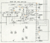
Those jumpers appear to be the unregulated power supply connections to the output transistor collectors which are apparent in the large schematic.

Have you had a chance to look at the voltage drop across D3 yet?

upload_2020-1-25_13-15-33.png
 
I assume that those readings are in mV. A 1N4148 may have a slightly lower forward voltage which you can try but the change may or may not be significant. A Schottky diode such as a BAT46 should have a forward voltage of around 400mV which should drop the bias current.

The difference between your measured voltages for D1 and D3 may explain why the bias for one channel is lower than the other with the trimmers turned all the way down.
 
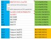
my DMM doesn't give the units, but I suppose that's .765 V


. . . I could try this, by jumping the legs of D3?
Yes, a short across D3 should drop the bias to 0. But, I would try a 1N4148 first if you have one. BTW, the receiver should be powered up on a DBT after these types of changes just to be safe.
 
Thanks again, I think I can come up with some 1N4148s today. Will report back on the effect of replacing D3.

Just to check my understanding, the spec indicates Vf forward voltage of 1V for 1N4148. Are we saying that an 1N4148 will drop the voltage by 1V compared to the current diodes which only drop it by .765 V, which in this case would be desired?

Here is where I see a 1V forward voltage for 1N4148:
https://www.mouser.com/ProductDetai...MIiv_iwbqf5wIVSrzACh1X9gs3EAAYAyAAEgKD9_D_BwE
 
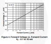
In this case, we are looking for a lower Vf than the currently installed diode. The 1V spec for the 1N4148 is likely a maximum value at a higher current level. The current in this circuit should be somewhere around 4 to 5mA so I'd expect that the Vf will be just under 700mV. This may not be enough to get you where you need to be but it should indicate how a change in D3 Vf affects bias.

If your meter has a diode function, you can check Vf before installing. As mentioned before, power up on the DBT and it doesn't hurt to have your voltmeter connected to measure bias as you apply power.

upload_2020-1-25_15-8-18.png
 
Thank you, LesE, for taking the time to explain that.
I did find some 1N4148s today and my DMM has a diode function.
Tomorrow I'll install them and see how close I can get to 20 mV on the adjustment.
I'll also report back and compare forward voltage drop between original diodes and the new IN4148s so we can understand how sensitive bias adjustment is to D1 and D3 with the old and new diodes.
 
Before going too far with the replacement, you may want to lift one end of the existing diode and measure Vf with you DMM diode test and compare it to the 1N4148. Unless Vf for the 4148 is less than the original diode, there is not point in proceeding with the replacement.

Upon further consideration of the Schottky diode, I expect that it's much lower Vf may also necessitate the replacement of the trimmer as well as R21 with a larger resistance value.
 
Back
Top Bottom