• The move to the new server is done. There are some software and database maintenance updates in process. This has us passing the hat around to help out. We appreciate any donations. Seriously, even a dollar helps. The payment page may be found here - https://www.audiokarma.org/support.html

New to me AU-666

bhairavi

AK Subscriber
Subscriber
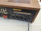
Got a 666 in the mail from Japan. Normally these would be JDM but I spied that this one happened to have the multiregion block on the rear.
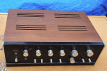
1784825725741.png
1784826694398.png
When I opened it up, interestingly, judging by the red sticker on the inside, the input voltage had never been changed and was set to 117V. So not sure what is the providence of this amp, but seems like it went to Japan from N America...


Blue tape still on it and in fair condition, but:

1784825766915.png

Ouch.

Start of the repair:
1784825795479.png

Also the seller left RCA jacks in when they shipped it, and as a result:
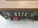
1784826808817.png
I think I have a good idea of how to fix this too but it will have to wait.


Also has some corrosion but bringing it up on DBT, we're getting clear sound out of both channels.
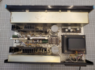
1784825844637.png

Thankfully like the 555A, just about everything on this is modular, so easy removal of the pcbs. Recap started:
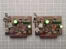
1784825894476.png


After a bit of reading, I think I'd like to remove the crowbar and subsonic filters on this thing. Still trying to figure out what needs to be disconnected and where...
 
Last edited:
Register to hide this ad
Remove C906, C908, & C910 ? - but following the AU-999 modifications sounds like the best idea.

Yes, for the Crowbar disconnection.
Wait so for the subsonic filter, keep the resistors, and no jumping?

Edit: reading more..

Anyone know if the preamp mods that the 999 gets applied to this amp?
 
I'm not sure the 999 mods are directly applicable to the 666, being a generation older. The 222, 555, 777 and 999 were one generation, followed on by the 555A, 666, and 888. Probably not a huge difference between these two lines in fundamental circuit design, but tread carefully.
 
I'm not sure the 999 mods are directly applicable to the 666, being a generation older. The 222, 555, 777 and 999 were one generation, followed on by the 555A, 666, and 888. Probably not a huge difference between these two lines in fundamental circuit design, but tread carefully.
Yeah no I did some more reading, I think the crowbar and subsonic filter reductions are the only thing that apply. Gonna upgrade the filter caps of course...
 
Wait so for the subsonic filter, keep the resistors, and no jumping?
By not removing the resistors I was thinking this would keep the signal levels similar, and give the 'pre-out' some buffering, additionally R908 is made redundant if the capacitors are removed. You might have to experiment with resistor values a bit, but you could reduce the resistor count (by one) and amalgamate R906 & R910, even if you leave them at their combined value (47KΩ + 47KΩ) = 100KΩ.
 
Last edited:
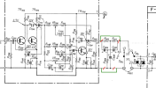
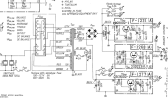
Wish I could understand what the heck is going on here:


View attachment 3806454


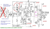
EDIT: looks like the additional resistors are there due to the substitution of modern high freq outputs. I think the differential inputs have added RC for fine-tuning?
Yes, the cap is for the reason myself I "think" a mechanical potentiometer is "noisy" by itself so I just guessed a cap would be beneficial to short some noise.
The 75 Ohms resistor is just to make the range the pot can tweak the DC voltage much lower and the sensitivity of the DC pot is much lower. So, it is much easier to set the DC offset within millivolts. So, it is not to be regarded as "RC" but as separate purpose of the R and C.

The resistors at the outputs I added because without the output stage would be "100% darlingtons" and those resistors minimize the impact of HFE differences of the upper pair of transistors versus the lower pair when crossing "zero voltage" on the current to be supplied by the voltage stage.
In the end, you see those resistors in just about any class AB alike main amplifiers but not in the AU666.


BTW I am not an EE and all changes were more or less GUESSING it all was for the better (disclaimer ;) )
 
Yes, the cap is for the reason myself I "think" a mechanical potentiometer is "noisy" by itself so I just guessed a cap would be beneficial to short some noise.
The 75 Ohms resistor is just to make the range the pot can tweak the DC voltage much lower and the sensitivity of the DC pot is much lower. So, it is much easier to set the DC offset within millivolts. So, it is not to be regarded as "RC" but as separate purpose of the R and C.

The resistors at the outputs I added because without the output stage would be "100% darlingtons" and those resistors minimize the impact of HFE differences of the upper pair of transistors versus the lower pair when crossing "zero voltage" on the current to be supplied by the voltage stage.
In the end, you see those resistors in just about any class AB alike main amplifiers but not in the AU666.


BTW I am not an EE and all changes were more or less GUESSING it all was for the better (disclaimer ;) )
Oh that's you! Thanks for the info.

What was the purpose of changing out all the transistors? Did you have blown outputs, or is it just that these are more robust?


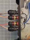
Where can I find those? I just started on a 551 receiver and was thinking I'd like to replace the terminals. I like that form factor.

Edit: only issue is you have to drill much larger holes than for the regular banana terminals - these are about 5/16" whereas the other ones are 5/32".
 
Last edited:
Pretty proud of this repair - rather than epoxying this cracked bakelite mount, I cut off a piece of somewhat stout sheet metal from the chassis of a junked piece of audio gear. Wrapped it in tessa tape to prevent shorts and slid it between the RCA channels, and under the metal brackets. No adhesive at all and now it's very solid!

 
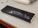
Man this thing needed work - did some rust/corrosion remediation in the chassis. It's only skin deep but I didn't want to leave it as is. Then cleaned up the faceplate with wd40 and a white scotch Brite, with glass fiber brush for the stubborn marks. Restor a finish in the cabinet now that the corner has been repaired. Not a perfect match, but it'll do!


20260726_151055.jpg20260726_154859.jpg


Edit: also deoxited the RCA jacks, and the contacts on the cartridge slots for the pcbs or whatever they're called. I supposed I should get the 555A ready but I hate unfinished projects. The only thing I hate more is waiting on Mouser orders!

Basically all I have left is the actual recap and a new rectifier bridge. Subsonic filter and crowbar circuits are out, new filter caps are in.
 
Last edited:
Well crap.


Got the mouser order in and finished off the recap. Brought it up on DBT > bright.

Took out the power amp fuses - still bright.

Took out the fuses that come right after the the rectifier - still bright.

Thought to check voltages at the rectifier - only in the 20s, and from the transformer only around 22 - but this is on DBT.

So risked it off DBT, and main 3A fuse blew.

I've double- and triple-checked all the caps in the power supply.

Could it be a bad rectifier? I can't think of what else could be cause the main fuse to blow short of the transformer itself.

This is what I got: https://www.mouser.com/en/ProductDetail/621-GBU1010
And the original rectifier is '5B2' rated 5A 200V


1785393725251.png
 
Hmm yes when I search that part number other people with the 888 have had the same problem.

But this is a new rectifier from mouser.

I guess the only way to find out is to disconnect it, put another fuse in, and see if the transformer blows the fuse even when it's unconnected to the rectifier... The other thing that is upstream of the transformer/rectifier is the cap I replaced across the power switch, X2 rated.

But now that I look at the schematics closely, I'm confused. The fuses I took out only go to the +/- rails of the outputs, the ones that supply the phono stage/preamp are still active..
 
Last edited:
Back
Top Bottom