• The move to the new server is done. There are some software and database maintenance updates in process. This has us passing the hat around to help out. We appreciate any donations. Seriously, even a dollar helps. The payment page may be found here - https://www.audiokarma.org/support.html

New to me AU-666

The resistors at the outputs I added because without the output stage would be "100% darlingtons" and those resistors minimize the impact of HFE differences of the upper pair of transistors versus the lower pair when crossing "zero voltage" on the current to be supplied by the voltage stage.
In the end, you see those resistors in just about any class AB alike main amplifiers but not in the AU666.
^Suspect that the 'base stopper' resistors you added might be the ticket here since my drivers are modern but my outputs are old..


LLM suggests checking zobel network..
 
Well I tried adding resistors across the BE of the outputs, and it helped significantly, but didn't get rid of the ringing completely.

Alternative suggestion was snubber caps to the drivers. I don't have any small enough. At this point I'm just working off what AI is telling me, doesn't feel very good, very likely to send me down the wrong rabbithole.

I've spent way too much time on this and half feel like throwing this thing in the the trash.. Probably should walk away for now.
 
I can’t remember on the 666 but I recall on the 999 it had quiet a few carbon resistors that had drifted a lot on the amp modules, might be worth checking some values on any carbon resistors here
 
I can’t remember on the 666 but I recall on the 999 it had quiet a few carbon resistors that had drifted a lot on the amp modules, might be worth checking some values on any carbon resistors here
My au 999 had a open carbon resistor on F1230, which supplies negative voltage. No visual damage, found when ohm checking all resistors during the re-cap.
 
Well I tried adding resistors across the BE of the outputs, and it helped significantly, but didn't get rid of the ringing completely.

Alternative suggestion was snubber caps to the drivers. I don't have any small enough.
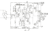
I humbly suggest it might be a good idea to try a test run with the feedback path open. Oscillating starts on the negative half cycle and quits when the upper driver transistor has taken over on the other half cycle. I'd pull R819 and C823, run the amp as before and look at the outputs to see if you've killed the oscillation. TR803 and TR805 have a fun little positive local feedback thing going which tends to excite oscillation. I think there's a value off in one of the feedback network components or possibly too much gain in one of those transistors.

Unfortunately (for this issue, not for me :biggrin: ) I'm off to go fishing so my response time will lag....a lot
 
I can’t remember on the 666 but I recall on the 999 it had quiet a few carbon resistors that had drifted a lot on the amp modules, might be worth checking some values on any carbon resistors here

My au 999 had a open carbon resistor on F1230, which supplies negative voltage. No visual damage, found when ohm checking all resistors during the re-cap.

Checked all the resistors on both boards and also the negative/positive filter boards. On the filter boards the large resistors have drifted a bit, around 20%.

I humbly suggest it might be a good idea to try a test run with the feedback path open. Oscillating starts on the negative half cycle and quits when the upper driver transistor has taken over on the other half cycle. I'd pull R819 and C823, run the amp as before and look at the outputs to see if you've killed the oscillation. TR803 and TR805 have a fun little positive local feedback thing going which tends to excite oscillation. I think there's a value off in one of the feedback network components or possibly too much gain in one of those transistors.

Unfortunately (for this issue, not for me :biggrin: ) I'm off to go fishing so my response time will lag....a lot

Well when I took out R819 and C823 (15pf, on the underside of the board) the oscillation went away but now there is a major hum.

R819 tests good. I can't tell if the 15pf tests bad or if my transistor tester is unable to read such small values. The fluke DIMM definitely can't resolve to this level.

I'll be able to get some replacements tomorrow and see that does.

How would I tell if the gain was 'too' high for the circuit on any of these transistors?
 
Checked all the resistors on both boards and also the negative/positive filter boards. On the filter boards the large resistors have drifted a bit, around 20%.


Well when I took out R819 and C823 (15pf, on the underside of the board) the oscillation went away but now there is a major hum.

R819 tests good. I can't tell if the 15pf tests bad or if my transistor tester is unable to read such small values. The fluke DIMM definitely can't resolve to this level.

I'll be able to get some replacements tomorrow and see that does.

How would I tell if the gain was 'too' high for the circuit on any of these transistors?
How different is the gain from the originals? I remember the flying saucer to be low gain. I’ve never tried ksc2383 in that circuit can you try out ksc2690 or bd139?
 
I humbly suggest it might be a good idea to try a test run with the feedback path open. Oscillating starts on the negative half cycle and quits when the upper driver transistor has taken over on the other half cycle. I'd pull R819 and C823, run the amp as before and look at the outputs to see if you've killed the oscillation. TR803 and TR805 have a fun little positive local feedback thing going which tends to excite oscillation. I think there's a value off in one of the feedback network components or possibly too much gain in one of those transistors.

Unfortunately (for this issue, not for me :biggrin: ) I'm off to go fishing so my response time will lag....a lot
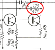
I am wondering about C809. As there is a 33 Ohms resistor to the base of the NPN driver, C809 may not help that much turning it off, who knows maybe a cap
of 1 microfarad or something between collector and emitter of the TR809 is better. In the end the new driver transistors are rather fast. Of course, my comment is just an uneducated guess.


BTW my way to protect these Sansui amps is using power resistors during tweaking bias and offset, no need for the dbt then.
I do not know whether it would affect oscillation. If fighting oscillation, you will have to try different loads (or at least load and no load) anyway.
I used blown fuses having 390 ohms resistors soldered sideways.
2018_1210_211831.JPG
 
Last edited:
Checked all the resistors on both boards and also the negative/positive filter boards. On the filter boards the large resistors have drifted a bit, around 20%.


Well when I took out R819 and C823 (15pf, on the underside of the board) the oscillation went away but now there is a major hum.

R819 tests good. I can't tell if the 15pf tests bad or if my transistor tester is unable to read such small values. The fluke DIMM definitely can't resolve to this level.

Don't rush to judgement about C823 &/or R819 being 'the' problem, it's more that you now know more about where to look. Breaking the feedback loop is a way to remove some very hard to intuitively understand circuit behavior (frequency dependent) by simplifying things. One effect of removing the feedback is that the now 'open loop' gain is higher, so no surprise that the hum is louder. But where is the hum coming from and what's different about the components in that feedback signal path between channels are a couple of good things to dig in to.

I see I missed a connection for so my comment about positive feedback between TR803 and TR805 is of the mark.

Closing the loop again is the way to test your possible fixes

Did you do hfe matching for the 2 transistors at the front end of the amp? TR801/803?
 
Last edited:
.. At this point I'm just working off what AI is telling me, doesn't feel very good, very likely to send me down the wrong rabbithole...
That it will certainly do. It will create solutions for you based on nothing that will lead to nowhere. Whenever it tells you to check the Zobel, you know it doesn't have a ****ing clue..
 
Don't rush to judgement about C823 &/or R819 being 'the' problem, it's more that you now know more about where to look. Breaking the feedback loop is a way to remove some very hard to intuitively understand circuit behavior (frequency dependent) by simplifying things. One effect of removing the feedback is that the now 'open loop' gain is higher, so no surprise that the hum is louder. But where is the hum coming from and what's different about the components in that feedback signal path between channels are a couple of good things to dig in to.

I see I missed a connection for so my comment about positive feedback between TR803 and TR805 is of the mark.

Closing the loop again is the way to test your possible fixes

Did you do hfe matching for the 2 transistors at the front end of the amp? TR801/803?
Tr801/803 are 992 and hfe is 330/338

Tr805/807 are 2383 and hfe is 202/202, and I tried replacing them with BD139 with hfe of 130/130.

Replaced 15pf caps across R819 with new ones.

Also tried adding 47pf caps across BC of the drivers (TTA/TTC004B) (this was an LLM suggestion).

No change in oscillation on the rise.

The amount of oscillation almost completely disappears when I increase the volume of the input to max (using main in function so nothing in the preamp muddies the picture).
 
Last edited:
You could play with the Miller cap to see if the oscillation goes away. Usually increasing it helps, but I had one case (HK 330B) where decreasing it helped after transistor changes. Oddly enough, this cap is not present in the schematic pic you provided.

miller.PNG
 
You could play with the Miller cap to see if the oscillation goes away. Usually increasing it helps, but I had one case (HK 330B) where decreasing it helped after transistor changes. Oddly enough, this cap is not present in the schematic pic you provided.

View attachment 3812994
Wait so is that an alternate schematic?

And I would be trying different values across the BC of the VAS transistors Tr805/807? Meaning try changing values at C805 or C811?


1785917529652.png
 
Downloaded it from hifiengine, "alt scan" -version. In any case the Miller cap should be there, or it would be an odd design.

Yes, different values for the cap across the BC of VAS (not C805 nor C811). Try increasing it first, incrementally.
 
Schem of the pow amp. I see that C811 is 220p here:

It worked! So on my amp boards there is a 100pf at C811, but an identical cap in parallel on the underside = 200pf. There was no 47pf, and when I added this (BC of Tr807) the oscillation disappeared, and sine wave is clean at low-medium volumes.

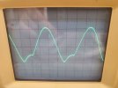
BUT, at high volume, there is still distortion, and the output looks like this:


20260805_121612.jpg


This is BOTH channels, and the preamp is clean. So what the heck could it be now that is affecting both poweramp channels??
 
That's unhealthy looking sine wave. Obviously something wrong with the pnp-side. Have you checked where the signal gets distorted?
 
That's unhealthy looking sine wave. Obviously something wrong with the pnp-side. Have you checked where the signal gets distorted?
As in probe using the scope? Will do that next. I wonder if it's the PNP outputs? I replaced the 2SD188 with 2SD188A that I had from another amp but left the PNP as their hfe was fine in the 70s...

If it's the outputs then I should see a clean wave everywhere else in the amp board, yeah?
 
On a second thought, bad signal is fed back via the feedback loop, so it isn't that simple. Test without the outputs to see what the signal looks like at the drivers, perhaps?
 
Back
Top Bottom