• The move to the new server is done. There are some software and database maintenance updates in process. This has us passing the hat around to help out. We appreciate any donations. Seriously, even a dollar helps. The payment page may be found here - https://www.audiokarma.org/support.html

New tubester in over my head? Magnavox 175-67

1962 RCA

New Member
Hi,
Been getting into this whole tube thing after I picking up a 1962ish RCA with a 6bq5 PP amp. I had the amp and tuner gone through and recapped by an electronics trade school student who did some really nice work for me. That stereo is my family daily driver and my kids love playing records and that makes me very happy. My tech resource is not taking on any new projects so I decided to try a restore of a 1959 magnavox dual chassis for my sister. We bought it on CL and it was working minus the record player. So I have replaced all the capacitors with carefully selected new ones from Mouser and I think I am getting close. My problem is with the can capacitors. I can find no markings indicating what lug is what value. I can not find any symbols that correspond to the values and symbols on the side of the can. I figured I would need to figure this out using deductive reasoning and a schematic. Unfortunately I have not been able to find a schematic that is clear enough to get me there. Is that how you would go about replacing the can caps? From a good schematic? By the way I also picked up a tabletop magnavox that has what I believe is a single ended pentode and two full range six inch speakers. I am shocked at how good it sounds. It is my new computer speakers! After the 175-67, that thing is going to get the works! Is already sounds so good.
 
Register to hide this ad
My problem is with the can capacitors. I can find no markings indicating what lug is what value. I can not find any symbols that correspond to the values and symbols on the side of the can. I figured I would need to figure this out using deductive reasoning and a schematic. Unfortunately I have not been able to find a schematic that is clear enough to get me there.

First, welcome to AK!

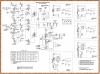
Here's the Sams for that model. It can be enlarged to show detail.

If you're replacing the original can sections with individual caps just install them as shown in the schematic. Make sure you clip off the center tabs of the existing cans so they aren't connected to anything. You can leave the can in place to preserve the original appearance and the negative leads from the individual caps can be connected to the mounting tabs of the original can.

If you bought new cans to replace the original cans they should have some type of marking next to the connectors that corresponds to the values on the side. They might be hard to see but if they're not there you have a problem unless all the sections are the same value. If that's the case it doesn't matter which section gets connected in which order. If the sections are different values and there are no markings I'd suggest you return the cans.

I always suggest using individual caps anyway because they are waay cheaper and you can choose caps with better specs than the ones typically in replacement cans. When I order new caps I choose ones rated at 105 degrees for 10,000 hours.

Shipping charges will inflate the cost of a small parts order considerably. Here's how to get free shipping from Digi-Key:
http://www.audiokarma.org/forums/in...hipping-on-parts-orders.739513/#post-10018562
 

Attachments

First, welcome to AK!

Here's the Sams for that model. It can be enlarged to show detail.

If you're replacing the original can sections with individual caps just install them as shown in the schematic. Make sure you clip off the center tabs of the existing cans so they aren't connected to anything. You can leave the can in place to preserve the original appearance and the negative leads from the individual caps can be connected to the mounting tabs of the original can.

If you bought new cans to replace the original cans they should have some type of marking next to the connectors that corresponds to the values on the side. They might be hard to see but if they're not there you have a problem unless all the sections are the same value. If that's the case it doesn't matter which section gets connected in which order. If the sections are different values and there are no markings I'd suggest you return the cans.

I always suggest using individual caps anyway because they are waay cheaper and you can choose caps with better specs than the ones typically in replacement cans. When I order new caps I choose ones rated at 105 degrees for 10,000 hours.

Shipping charges will inflate the cost of a small parts order considerably. Here's how to get free shipping from Digi-Key:
http://www.audiokarma.org/forums/in...hipping-on-parts-orders.739513/#post-10018562

Wow that is a much better copy! Thanks for that. Since the can is a 40, 30, 10, at 450 volt and a 20mfd at 25 volt. I guess that makes this a "BB" or maybe a "EE" version. Do you think it would be a bad idea to just replace all of them all with 40uf at 450 volt capacitors? I am planning on installing a terminal strip and moving the old and new components to get away from the old multi can capacitor.
 
Wow that is a much better copy! Thanks for that. Since the can is a 40, 30, 10, at 450 volt and a 20mfd at 25 volt. I guess that makes this a "BB" or maybe a "EE" version. Do you think it would be a bad idea to just replace all of them all with 40uf at 450 volt capacitors? I am planning on installing a terminal strip and moving the old and new components to get away from the old multi can capacitor.
Are you using individual caps or are you installing a new can?

If you're replacing the can sections with individual caps, you'll find that modern caps come in slightly different values.

I'd suggest using a 47uf for both C1A and C1B. For C1C you could keep it at 10uf or go up to a 22uf. Those three sections should all be rated at 450v, same as the stock can. For C1D, which is the 6V6 cathode bypass cap, I'd go with 22uf and up the voltage to 35v. For C2 and C3 use 22uf 25v parts.
 
The can capacitors phenolic wafer does have the symbols you just have to bend the lugs to see them. Stick closely as you can to the original specs.
 
I also own a 175-67 amp. The phenolic wafer does indeed show the symbols as Cademan stated. You just have to bend the lugs to see them.

I would go with FlaCharlie's advice and stay as close as possible to the original specs as sometimes going over the rated voltage or uF can cause motor boating.
 
I also own a 175-67 amp. The phenolic wafer does indeed show the symbols as Cademan stated. You just have to bend the lugs to see them.

I would go with FlaCharlie's advice and stay as close as possible to the original specs as sometimes going over the rated voltage or uF can cause motor boating.

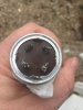
Man if it is there I can’t find it. I would love to find it. Here are a couple of pics.
 

Attachments

  • EE1F7379-1973-48AA-9993-90D9B6DDFC46.jpeg
    EE1F7379-1973-48AA-9993-90D9B6DDFC46.jpeg
    42 KB · Views: 37
Man if it is there I can’t find it. I would love to find it. Here are a couple of pics.
Hmmm. They're usually stamped into the surface of the brown phenolic but I don't see anything either. Makes me wonder if this is the original can but any replacement should have them too.

The only reason I can think of that they wouldn't be there is if all four sections were the same value, in which case there would be no need to mark them. What values are stamped on the side of the can?

Either way, it doesn't really matter. Just go with the values I suggested earlier.
 
Man if it is there I can’t find it. I would love to find it. Here are a couple of pics.
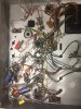
Here is where I am at. I added 4 one post terminals that correspond to each capacitor lug I don’t suppose anyone here knows the layout well enough to say what cap goes to what lug? I am not great at reading schematics.
Hmmm. They're usually stamped into the surface of the brown phenolic but I don't see anything either. Makes me wonder if this is the original can but any replacement should have them too.

The only reason I can think of that they wouldn't be there is if all four sections were the same value, in which case there would be no need to mark them. What values are stamped on the side of the can?

Either way, it doesn't really matter. Just go with the values I suggested earlier.
40 mfd at 450 volt and that is the half circle
30 mfd at 450 volt is the square
10 mfd at 450 volt is the triangle
20 mfd at 25 volt has no symbol
 

Attachments

  • 74BD3F59-719A-412C-B8DB-FBF5160079CF.jpeg
    74BD3F59-719A-412C-B8DB-FBF5160079CF.jpeg
    69.4 KB · Views: 23
  • 60900D7C-47A6-4927-98DC-52C6C97BACA1.jpeg
    60900D7C-47A6-4927-98DC-52C6C97BACA1.jpeg
    55.2 KB · Views: 21
I can start with the two lugs that were connected to the choke. I also have the point of reference of the 100k resister. I think the symbol with the curly lines and the flat line is the choke. one of the lugs goes to one of the pins of the 5u4gb tube socket. The 30 is connected to the other side of the choke and is also connected to one side of the 100k resister.
 
Yes, very unusual having no symbols.

Right after pin #8 of the 5U4 tube is the first 40MFD @ 450VDC. One end of the choke goes to this connection. The other end of the choke connects to the 30MFD @ 450VDC. From the 30MFD is the output transformers CT or Center Tap (red wires). The schematic shows this as the 345 volt source.

A 100K, 1 watt resistor connects from the 30MFD positive lug to the 10MFD positive lug. The 10MFD is the 250 volt source. This connects into the preamp section and 12AX7 tubes. You will need to know how to read a schematic if you didn't happen to mark this properly after taking the old capacitor out.

The 20MFD @ 25VDC is the cathode bypass capacitor. The positive lug of this one connects to the cathodes of all four 6V6 tubes (pins 8) and can be an individual capacitor. They can all be individual capacitors.

Magnavox 175.PNG
 
Last edited:
I am not great at reading schematics.
Schematics look intimidating at first but if you can read a road map you can read a schematic.

Just think of the lines (which could be wires, or the leads of a resistor or cap, etc) as roads and each component (resistors, capacitors, pots, transformers, etc) as towns along the road. If you follow a particular "road" you will, at some point, come to the "town" shown on the schematic.

The actual distance between "towns" will vary considerably so forget about whether the "road" between them is short or long on the schematic. Distances are not accurate. If you follow the road, though, you will eventually find the town.
 
I can start with the two lugs that were connected to the choke. I also have the point of reference of the 100k resister. I think the symbol with the curly lines and the flat line is the choke. one of the lugs goes to one of the pins of the 5u4gb tube socket. The 30 is connected to the other side of the choke and is also connected to one side of the 100k resister.
Sometimes a schematic can be hard to understand when looking at the real circuit. So, it is sometimes better to draw the physical layout of your amps components by hand and carefully number each resistor value, or cap and the layout and color of the various wires. I find this exercise really helps to ingrain the circuit layout in my head and also easier to understand the schematic. Many times there are unused taps on tubes sockets, especially the rectifier tube socket that will be a convenient spot for making connections.
 
I think the cap value symbols were stamped onto the lugs themselves,... that look to have been nipped off.
That seems plausible. They were covered with solder. I nipped off the lugs and took the old lug with the old attached wires over to my terminal strip and attached the whole thing to my terminal. I then used that as a point to attach the appropriate capacitor.
 
Yes, very unusual having no symbols.

Right after pin #8 of the 5U4 tube is the first 40MFD @ 450VDC. One end of the choke goes to this connection. The other end of the choke connects to the 30MFD @ 450VDC. From the 30MFD is the output transformers CT or Center Tap (red wires). The schematic shows this as the 345 volt source.

A 100K, 1 watt resistor connects from the 30MFD positive lug to the 10MFD positive lug. The 10MFD is the 250 volt source. This connects into the preamp section and 12AX7 tubes. You will need to know how to read a schematic if you didn't happen to mark this properly after taking the old capacitor out.

The 20MFD @ 25VDC is the cathode bypass capacitor. The positive lug of this one connects to the cathodes of all four 6V6 tubes (pins 8) and can be an individual capacitor. They can all be individual capacitors.

View attachment 1464992
I think i was able to use the process of elimination but without knowing the lug values, it is impossible to know which one of the two possible configurations in the schematic is the right one. one schematic show the 40uf going to the lug attached to the 5u4 tube and the 30 on the other choke attached lug. The other schematic breakout shows those two reversed. I did not take that into account so I put a 33uf on the post not attached to the tube. The original advice to use 47uf for both would have been better. it would have eliminated the possibility using a cap that was 7uf below spec. i have another 40uf that I can replace the 33uf. i might also put in a 10uf in parallel if it is long enough to reach. after that I am almost done! I have a thermistor to install and I still need to replace the power cord with a 3 pronger and fuse.
 
I want to say THANK YOU! to all who have helped me do this. I am feeling much more confident that I can work through any curveballs with the help of this board and the generous people here.
 
You can be confident that these values:
40uF
30uF
10uF
20uF
are correct for the 175-67. My 175-67 has the same.

Also, you can use 33 or 47 in place of the 40. I would use 47.
 
Back
Top Bottom