Hi all; I just picked up a Newmar 115-12-8 PS from a radio swap meet. The problem is that it is putting out about 31vdc. It should be about 12.8vdc. Only spent $10 for it so not the end of the world. What would cause the over voltage on the output? Thanks for any help.:scratch2:


You are using an out of date browser. It may not display this or other websites correctly.
You should upgrade or use an alternative browser.
You should upgrade or use an alternative browser.
Newmar 115-12-8 Power Supply help
- Thread starter jim249
- Start date
Register to hide this ad

Trio
Super Member
Rectifiers may have shorted out, the regulator may finis. If it were mine, and I salvaged a supply that was in a similar condition a few years back. I simply isolated the transformer windings to see what voltage that was and built my own rectifier bridge and regulator. in the long run it was probably less time to do it that way as nothing really stood out as a point of failure even checking a few likely components with nothing glaringly wrong or out of spec.
Taking a closer look, it appears that the two small diodes have gotten quite hot and of the two lager ceramic looking diodes, 1 is still green in color while the other is black. Looks like a future project here. Could something else have gone bad to take out the diodes or are they just old. The two power transistors are Motorola 2n3055. Thanks for any help.

Do you have a schematic? The BAMA site might have it.
This is the only documentation I can find for this. It does give theory of operation at the top right of the first page. Bama has no Newmar postings. Thanks
http://www.newmarpower.com/Manuals/M-PWRSUP-G.pdf
http://www.newmarpower.com/Manuals/M-PWRSUP-G.pdf
I was thinking this was vintage but Newmar is still around. You might contact their tech support via email and ask if they are willing to share the schematic. It might be a help with troubleshooting. Not that I'm the guy for that, but that's what the smart ones around here always ask for. 
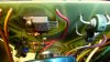
Here are some pics of the circuit board. I am now thinking that the diodes could be ok. The small ones have blackened leads but the body looks ok, the larger diodes I am guessing that the one that is grey colored is supposed to be that way. What I did notice is that 3 resistors are fried and a circuit trace has burned through. The first pic shows two burned resistors, side by side that look to be the same value, the second pic shows the third singed resistor by the regulator?, and the third pic shows the burned through circuit trace. This might be headed for the recyclers. Thanks
Attachments



petehall347
the brandy coffee man
wont cost much to rebuild that circuit .. nice project ..
petehall347
the brandy coffee man
where do those wires go that the resistors connect to ?
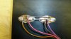
Those two wires go to both of the power transistors, one wire to each one. See pic. The other fried resistor is connected between the center lug and outer lug of the regulator?. See pic. The one lead of the resistor is just below and to the right of the nut, the other end is to the left. The burned trace, one end goes to the positive 12vdc output jack and the other end goes to a resistor which looks ok. It is a red light gauge wire so I doubt it is the one carrying the actual load. Sorry for the delay in response, I am irrigating the pasture for the next few days also. Thanks
Attachments

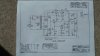
Here is the schematic. R1 got hot, R3 and 4 are blackened and connection point L is where the circuit trace burned through. The spec sheet mentions a fast blow fuse on the output only, a slo-blow fuse was installed. The supply is rated at 5 amps continuous 8 amps peak. I am guessing that Q1 and 2 survived since they are rated for 15 amps. So it looks like I will replace R1,3, and 4 and Q3 TIP 29 and a jumper on the board. Thanks for the help.
Attachments
Last edited:
Cool. So maybe someone drove it too hard with the wrong fuse in it. Hope that turns out to be the case.
Hard to design something to work when people don't follow directions...
Hard to design something to work when people don't follow directions...
petehall347
the brandy coffee man
with r3 and r4 being cooked then i would think the voltage out should be pretty low ...
it would be worth checking those power transistors for short ...
i would be going over everything .or simply replacing all semiconductors .
it would be worth checking those power transistors for short ...
i would be going over everything .or simply replacing all semiconductors .