• Please note that Audiokarma will be offline briefly for updates early on Monday morning, September 28th.

Nikko Alpha II - full recap and issue

BobCT

New Member
Hi, my first post here (and first recap job). I have a Nikko Alpha II which worked fine but decided to do a full recap on just given the age. I ordered a full "kit" which included the power stage caps. I'm done, at the testing stage but of course it's not working :(

Can someone take a look at the video (youtube link below) and let me know where I should start? It looks like a blew the fuse at the end of the video, I haven't checked yet. No smoke or any weird smells. Should I try an audio source on the left channel just to see if I have any output first?


thanks!
Bob
 
Register to hide this ad
Why aren't you using a DBT?
Did you check any voltages? Did you even check your work?

This is why I hate kits, it makes people think it's a simple job and it's not.
Also it didn't even include the protection relay and i doubt it had any transistors.
 
Correct, the kit did not include transistors or protection relay. I don't have a DBT, I guess I should have put one together now. I just verified that the Right channel blew a fuse, the left channel does work and has good sound output so at least it's not both sides. I had a hum previously, that appears to be gone at least on the one good channel I can hear.

I did a long visual inspection and used an old set of speakers as my test. I'm doing this for the first time so I knew there would be a learning curve and here I am :)

What's the best way to troubleshoot at this stage? Does the hum/bouncing VU (until fuse blows) point to anything specific? I replaced:

Power stage caps (2 each side)
Caps on the both main Amp boards
Protection caps
Regulator caps

Is there anything on that list that I can rule out to narrow down the search?

thanks
Bob
 
Last edited:
I did not do this check.... since it's blowing a fuse but takes a minute, am I doing more damage by testing live?
 

Attachments

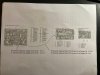
  • schematic.jpg
    schematic.jpg
    92.2 KB · Views: 30
Correct, the kit did not include transistors or protection relay. I don't have a DBT, I guess I should have put one together now. I just verified that the Right channel blew a fuse, the left channel does work and has good sound output so at least it's not both sides. I had a hum previously, that appears to be gone at least on the one good channel I can hear.

I did a long visual inspection and used an old set of speakers as my test. I'm doing this for the first time so I knew there would be a learning curve and here I am :)

What's the best way to troubleshoot at this stage? Does the hum/bouncing VU (until fuse blows) point to anything specific? I replaced:

Power stage caps (2 each side)
Caps on the both main Amp boards
Protection caps
Regulator caps

Is there anything on that list that I can rule out to narrow down the search?

thanks
Bob
Check your work. See if any caps were installed backward (don't depend on the board's silk screening; they are occasionally wrong) and carefully inspect your soldering for bridges.

Don't power it up again without a DBT.
 
Hi, my first post here (and first recap job). I have a Nikko Alpha II which worked fine but decided to do a full recap on just given the age. I ordered a full "kit" which included the power stage caps. I'm done, at the testing stage but of course it's not working :(

Can someone take a look at the video (youtube link below) and let me know where I should start? It looks like a blew the fuse at the end of the video, I haven't checked yet. No smoke or any weird smells. Should I try an audio source on the left channel just to see if I have any output first?


thanks!
Bob
Bob, it's a little late but I always recommend that you learn on things you don't care about. As I often say, there's a reason surgeons learn on cadavers.
 
agreed, lesson learned.... I went right for the live body. Frustrating because the other channel is fine so at least the guy lived for a few mins :)
I guess the fact that one channel is good is a plus and it was known working before so it's definitely something I had my hands on. I will check the caps. In the meantime:

I tested it a few more times (this time replaced 5a fuse w/ 1a and it's progressed to a dead short/fuse blows immediately). I now have some damage on the Regulator board so something is really off. No more live testing.

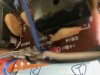
Do you know what C814 is called? What component is that? In the top pic you can see the damage in the right hand corner. That's the bottom of the regulator board under C814. C811 is a better view of the component but the damage seems to be limited to 814.


regboard_btm.jpg


regboard_top.jpg

As part of the kit, the power caps only had 2 legs instead of 4. It looks to me like the legs were bridged on the original caps so it was only another connection point, not an electrical change. I just want to make sure that's not a smoking gun. The fact that one channel works makes me think no but that's the only point worth mentioning. Yes, will start inspecting the caps one by one and did rely on the board markings.
 
agreed, lesson learned.... I went right for the live body. Frustrating because the other channel is fine so at least the guy lived for a few mins :)
I guess the fact that one channel is good is a plus and it was known working before so it's definitely something I had my hands on. I will check the caps. In the meantime:

I tested it a few more times (this time replaced 5a fuse w/ 1a and it's progressed to a dead short/fuse blows immediately). I now have some damage on the Regulator board so something is really off. No more live testing.

Do you know what C814 is called? What component is that? In the top pic you can see the damage in the right hand corner. That's the bottom of the regulator board under C814. C811 is a better view of the component but the damage seems to be limited to 814.


View attachment 2785485


View attachment 2785487

As part of the kit, the power caps only had 2 legs instead of 4. It looks to me like the legs were bridged on the original caps so it was only another connection point, not an electrical change. I just want to make sure that's not a smoking gun. The fact that one channel works makes me think no but that's the only point worth mentioning. Yes, will start inspecting the caps one by one and did rely on the board markings.

C814 is just a ceramic cap. That 4 leg thing is your full bridge rectifier and the put a ceramic capacitor across all four of the diodes that are within it. So C814 is that little tan guy, not the bigger 4 legged black square thing. I can’t tell by the pic as it’s too blurry, but generally one corner of the rectifier is slanted instead of a 90 degree corner, to help orientate in some instances.

Like this guy is notched
5C4948A2-94A3-4F3C-A103-2F4E3B7A6DE7.jpeg
Dan
 
agreed, lesson learned.... I went right for the live body. Frustrating because the other channel is fine so at least the guy lived for a few mins :)
I guess the fact that one channel is good is a plus and it was known working before so it's definitely something I had my hands on. I will check the caps. In the meantime:

I tested it a few more times (this time replaced 5a fuse w/ 1a and it's progressed to a dead short/fuse blows immediately). I now have some damage on the Regulator board so something is really off. No more live testing.

Do you know what C814 is called? What component is that? In the top pic you can see the damage in the right hand corner. That's the bottom of the regulator board under C814. C811 is a better view of the component but the damage seems to be limited to 814.


View attachment 2785485


View attachment 2785487

As part of the kit, the power caps only had 2 legs instead of 4. It looks to me like the legs were bridged on the original caps so it was only another connection point, not an electrical change. I just want to make sure that's not a smoking gun. The fact that one channel works makes me think no but that's the only point worth mentioning. Yes, will start inspecting the caps one by one and did rely on the board markings.
You HAVE to make a dim bulb tester. Even with 1 amp fuses you can cause more damage each time you power it up. While a fuse appears to blow in an instant, in electronic terms it's an eternity. The DBT prevents damage by the bulb filament glowing brightly, which not only gives a good visual cue but limits the current to the unit under test.

Do not power it up again without a DBT, or you're just asking for even more trouble than you've already got.
 
Thanks, I appreciate the replies. I know more now that I've looked closer. I will not power it up again w/o a DBT (it is on the way). I've done a couple of things:

- I went through every cap I replaced and verified the +/- is correct (comparing the schematic and the board markings) and all were correct. I had one cold solder joint and fixed that. I assume that wouldn't be the root cause.

- Upon closer inspection, C814 (thank you Saabracer) was not visibly damaged. Right next to that are the terminal strip solder joints and it looks like that took the "hit". I cleaned that up, reflowed those connections so it should be good now. That's the blurry pic I posted before.

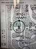
- On the Main cap board, should the C701 and R701 be connected? In one of the pics I took before I started anything, there is solder flow between the two on (left and right boards) which I replicated. I just want to be 100% that is correct. Here is a pic of the schematic and:

resistor.jpg


bottom_board.jpg

And here are the solder points on the back of board. You can see the three connections just to the left of the word "IN" above. That's the C701 cap connected to one leg of the R701 resistor. It's the same on both boards and it looked like that originally. I just want to make sure I didn't miss something here.

I won't do it again but if I powered it up, the 5a fuse would instantly blow (1a last time). I replaced caps on the Regulator board, Protect board and two Main amp boards. In terms of narrowing down the problem, can I rule any of those OUT? The other channel is fine.

Also, you can see the glue on the board above. I read that can be conductive over time and seems to affect all 80's era Nikko units. Should I be trying to scrape that off at least between the solder points so there's no conductive path? I started to on the other board and it's easy to get down to bare copper. I don't think this is my issue but while it's apart....

thanks
Bob
 
Last edited:
Thanks, I appreciate the replies. I know more now that I've looked closer. I will not power it up again w/o a DBT (it is on the way). I've done a couple of things:

- I went through every cap I replaced and verified the +/- is correct (comparing the schematic and the board markings) and all were correct. I had one cold solder joint and fixed that. I assume that wouldn't be the root cause.

- Upon closer inspection, C814 (thank you Saabracer) was not visibly damaged. Right next to that are the terminal strip solder joints and it looks like that took the "hit". I cleaned that up, reflowed those connections so it should be good now. That's the blurry pic I posted before.

- On the Main cap board, should the C701 and R701 be connected? In one of the pics I took before I started anything, there is solder flow between the two on (left and right boards) which I replicated. I just want to be 100% that is correct. Here is a pic of the schematic and:

View attachment 2790158


View attachment 2790157

And here are the solder points on the back of board. You can see the three connections just to the left of the word "IN" above. That's the C701 cap connected to one leg of the R701 resistor. It's the same on both boards and it looked like that originally. I just want to make sure I didn't miss something here.

I won't do it again but if I powered it up, the 5a fuse would instantly blow (1a last time). I replaced caps on the Regulator board, Protect board and two Main amp boards. In terms of narrowing down the problem, can I rule any of those OUT? The other channel is fine.

Also, you can see the glue on the board above. I read that can be conductive over time and seems to affect all 80's era Nikko units. Should I be trying to scrape that off at least between the solder points so there's no conductive path? I started to on the other board and it's easy to get down to bare copper. I don't think this is my issue but while it's apart....

thanks
Bob
You're assuming the board markings are correct, and they may be. Or they may not be. Compare left to right channels to insure polarity of newly installed capacitors is correct.
 
on the board in question, I verified that both the board marking AND the schematic tied out (used one to verify the other) and then matched the caps. I will now compare that to the known working side... thanks
 
Since it only affects one channel it's fairly safe to rule out power supply. Keep the power off. Anytime something works and then not after you work on it, it's obvious it's something you did so go back over the right channel amp circuit, compare some resistance measurements to ground with the left channel starting with the output transistors one leg at a time and work back. Any measurements that are much different, investigate that further. Lifting a leg and re-measuring can lead you to the issue further. As advised before, get the DBT operational or leave the power off to avoid further damage. I just recapped my Nikko Alpha 230 along with several of my other pieces and no issues yet. I purchased my own caps, etc. from Mouser, DigiKey, Newark. I have a variac so I use that and slowly bring it up while watching the current draw. To turn it on full after such a major restoration is...well.....crazy but live and learn.
 
As an aside, I just picked up an Alpha 230 the other day and will recap that one as well. If you happen to have a list of caps, that would be great. One thing at a time :)

Yes, I have a DBT arriving tomorrow so not issue there. I appreciate the approach, fortunate to have a known good side. I'll start taking some measurements side to side and see what I come up with.

thanks
 
I'd like to find another 230. Mine has been amazing since I bought it new around 1984ish and the first time I've had it apart was a few weeks ago to do the recap.
I didn't change the big 15,000/71v caps but may sometime soon. Be sure to check the size before ordering those 15,000uf caps, especially the diameter. Makes things easier and looks nicer if you can get the same diameter.

Here's the list I made for the job. The capacitor brand and series is not written in stone. You may prefer another brand and anything of good quality would be fine. Lots of bi-polar caps in this amp.

Nikko Alpha 230
Service manual available here: https://www.hifiengine.com/manual_library/nikko/alpha-230.shtml

Amp PCB
C803, 804 - 1000/100v Nichicon UPW
C705, 706, 707, 708, 727, 728 - 100/25v Nichicon UFG
C721, 722, 725, 726 - 22/25v Bi-Polar. Nichicon UES
C723, 724 - 100/16v Bi-Polar. Nichicon UES
C743, 744, 745, 746 - 1/100v Nichicon UPW

Input PCB
C701, 702 - 2.2/50v Bi-Polar. Nichicon UES
These could also be film types but I didn't bother since I use the direct coupling so these are bypassed.

Regulator PCB
C810 - 100/16v Bi Polar UES
C807, 808 - 1/50v Bi-Polar. Nichicon UES or UDB
C818, 809 - 1/50v Nichicon UPW
C812 - 10/25v Nichicon UPW
C811 - 47/25v Nichicon UPW

Main power supply caps - 15,000/71 - CDE 383LX or Kemet (or any other decent cap)

Headphone/LED PCB
C813 - 47/16 Nichicon UPW
C814, 815 - 330/25v Nichicon UPW
C816 - 100/25v Nichicon UPW
C817 - 33/25 Nichicon UPW
 

Attachments

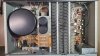
  • Top.jpg
    Top.jpg
    114 KB · Views: 26
Last edited:
Sorry, I typed “230” by mistake because I looked at a few. What I have is an Alpha 220. I’m sure this list will help someone doing the same. I’m still troubleshooting my Alpha II and bought this 220 so I can have some music while I’m working on the 220. It worked great for a few days and then horrible distortion and looking at caps now with two suspects.
Thanks
Bob
 
Sorry, I typed “230” by mistake because I looked at a few. What I have is an Alpha 220. I’m sure this list will help someone doing the same. I’m still troubleshooting my Alpha II and bought this 220 so I can have some music while I’m working on the 220. It worked great for a few days and then horrible distortion and looking at caps now with two suspects.
Thanks
Bob
Bob, there are more things that can fail in an amplifier besides capacitors. Is it affecting both channels?
 
Yes, it is both channels. It gets better when it's warmed up, listenable at low volumes. When it's cold, it sounds like both speakers are blown. I was going to start with the caps first (maybe not a bad idea anyway) but happy to take any advise on other areas to test. I did really good look for cold solder joints already.

thanks
Bob
 
"The 230 is electronically identical to the Alpha 220 except for some minor cosmetic differences". I just read this on another forum. They sure look the same from the pics I've seen. PW5599, maybe your cap list is the same or really close.
 
Back
Top Bottom