• The move to the new server is done. There are some software and database maintenance updates in process. This has us passing the hat around to help out. We appreciate any donations. Seriously, even a dollar helps. The payment page may be found here - https://www.audiokarma.org/support.html

Nikko Beta 40 relay not click. Need help.

I hadn't noticed, until Steve's comments, that the +15V supply is only half wave rectified - that could well explain some of the apparent voltage 'discrepancies'. I think some of us assumed it was a 'clean' dc supply.

A separate question though - have you already checked that the relay is actually the issue ? e.g., that you have audio signals up to the relay contacts ?
 
A separate question though - have you already checked that the relay is actually the issue ? e.g., that you have audio signals up to the relay contacts ?

Yes i did check the signal using DMM = AC mode:
Power main switch = ON
Bridge rectifier D801 D802 onboard.
Source = AUX (Android Frequency Generator apps)
Volume/Attenuator = max (clockwise)
Start from test point (Left CH PIN 7, Right Channel Pin 9) Until relay pin = 1.5vac
 
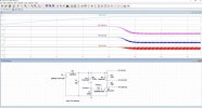
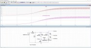
This was annoying me, so I just ran a quick LTSpice simulation for the relay circuit:

The voltage drop across the relay coil sits at 0V until the caps are charged (about 8" in the sim), then rises to ca. 8.3V over about 2" - BUT - with a continuous ca. 2V peak to peak ripple. The relay current correspondingly is ca. 10mA +/- ca.1.3mA ripple. The actual values may vary slightly from the sim results (different parts etc.), but that ripple's not going to vanish.

I suspect the relay is operating (or not) very close to it's 'lower' limit, vis a vis pull-in (8.3V is only ca. 70% of the nominal 12V relay coil voltage). It was probably designed to be at the lower end, to allow for a fast muting when switched off.

LT-Spice Relay-1.jpg

LTSpice Relay-2.jpg
 
Last edited:
One thin bugging me (well maybe more than one...) How low does the collector of Q901 go. You originally said 8.3 volts, but it should go down to near zero (less than one). Is it still around 8? If so, there is something wrong there. Also are you measuring the lead, or at resistor R903? Thinking R903 (220 ohm) could be off value, and taking voltage fromwrong side)
 
Assuming the simulation is anywhere near reality (and it should be), Q901(C) never drops to 0V. The voltage waveform @ Q901(C) is almost sawtooth (after ca. 10-12"), ranging from +0.5 to +2.2V. If that is the case, then a DMM won't give an accurate value anyway - although I'd indeed expect way lower than 8V
 
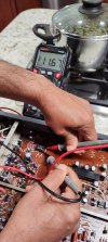
This is annoying. This AM I opened my Nikko BETA 20 that I restored recently. Also had the exact same issue prior to restoration. Replaced all the parts in the "mute" circuit after verifying the relay was OK. Works perfectly.
Voltage across coil after about 5 Secs: 11.67
Voltage on collector: 5.3VDC (KSC2383)

The circuit is very similar to OPs unit.
 

Attachments

  • IMG_20240726_073441623_HDR.jpg
    IMG_20240726_073441623_HDR.jpg
    87.6 KB · Views: 16
  • IMG_20240726_073502279_HDR.jpg
    IMG_20240726_073502279_HDR.jpg
    106.7 KB · Views: 14
  • IMG_20240726_073833391.jpg
    IMG_20240726_073833391.jpg
    100 KB · Views: 16
  • Screenshot 2024-07-26 075649.jpg
    Screenshot 2024-07-26 075649.jpg
    115.2 KB · Views: 18
Last edited:
This is annoying. This AM I opened my Nikko BETA 20 that I restored recently. Also had the exact same issue. Replaced all the parts in the "mute" circuit after verifying the relay was OK. Works perfectly.
Voltage across coil after about 5 Secs: 11.67
Voltage on collector: 5.3VDC (KSC2383)

The circuit is very similar to OPs unit.
The beta x0 series is a step sideways from the beta ii in quality, a step ahead in sound, two steps in complexity, but nobody did a damn thing about the relays. They still suck. They fail. They're not readily replaced. They're way more complex than they should be. It's an over engineered time delay circuit. There is really no reason to fight it. Jumper the relay and move along, or replace with a 555 circuit, which they should have done in the first place...

That being said... I have a fully functioning stock beta 40. I can take any voltages and such you may want this weekend, but it might be Sunday afternoon.
 
Looking at the simulation data and my own measurements from BETA 20, looks a possible cold solder joint somewhere in the circuit that fails to pass current. @ReisDaddy can you post pictures of the solder side?

@loudnoises - Agree but the fun part is to figure it out. Bypassing the relay would be my last option.
 
Last edited:
@Goldie99 Thank you for your time to make that simulation.

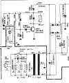
@p4spooky I found that Nikko Beta 20 is similar relay, but you post it faster.

Nikko Beta 20

nikko_beta-20-SM.pdf-image-007_crop.png
I dont have KSC2383 on hand. I'l try to find it.
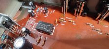
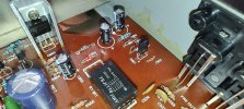
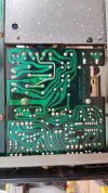
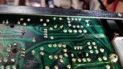
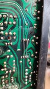
Here is the photos of the back of PCB

IMG_20240727_073255.jpg

IMG_20240727_073431.jpg

Its a bit hard to take the photo of the relay area, because of the shadow from the back panel.
I bring outside to make it clear (hope so)

IMG_20240727_073624.jpg

@loudnoises Yes, i really appreciate that.

My other question is, can we change the resistor of that R902 and R903 to make relay work?

Sorry if i missed a question from you guys, just let me know, ill reply.
 
I forget to mention that my wall plug is around 240vac and using step down 115vac
I bought the step down after i bought Nikko. Since im confused which to choose, Most step down here 110vac and the service manual is 120vac, so i bought 115vac.
Maybe it is the trouble?
 
Step down transformer probably is not the issue. (but I could be wrong.) Preamps usually have a lot of leeway in this respect.
One thought - there is a large screw in the middle of the supply board, which grounds the board to the chassis. Try loosening then tightening that screw. All kinds of weird things can happen if it were loose.
One last idea - Have you tried change D803 and C823? The reason I ask is that the ground path has to go through the D803 bridge. The power is only used by the headphone amp, and will not affect any other part of the circuit,
 
Just to give information,
If i pull Q901 from circuit,
Using DMM in circuit,
Pin E : Steady 0v
Pin C: Steady 15.4v
Pin B: from 0v then incremental around 20 sec to reach steady 8v.
Sorry to butt in here but I'm trying to follow along and there is something I'm not understanding here. Clearly my understanding of Zener diode function is faulty. The way I see it there should be 0v at the base of Q901 (if it is removed) until the capacitor charges and the voltage reaches the setting of the Zener diode. (6.2v in this case), then i would expect the voltage to keep increasing from there to 15.4v. Since it can't go anywhere. (The transistor is out). Why would it stop at 8v? What am I missing?
Thanks for any clarification!
Cheers...............................Todd
 
Sorry to butt in here but I'm trying to follow along and there is something I'm not understanding here. Clearly my understanding of Zener diode function is faulty. The way I see it there should be 0v at the base of Q901 (if it is removed) until the capacitor charges and the voltage reaches the setting of the Zener diode. (6.2v in this case), then i would expect the voltage to keep increasing from there to 15.4v. Since it can't go anywhere. (The transistor is out). Why would it stop at 8v? What am I missing?
Thanks for any clarification!
Cheers...............................Todd
Good question. My guess would be loading from the meter itself will keep it from going up further. A quick test would be to measure from the +15 supply, and see if the difference goes to zero (+15 on the zener.) Even a couple megOhms to ground should load the zener enough to work... But we digress.
 
See my voltages in the PIC. NOTE this is from NIKKO Beta 20. See the associated schematic I attached in my post. Please post the voltage readings from your unit. May be that might give us a clue. Did you replace the zener?

As suggested by @sregor tighten the ground screws

Note: Voltage measurements taken with black probe to ground. Exception is voltage shown across relay coil
 

Attachments

  • IMG_20240726_200452844.jpg
    IMG_20240726_200452844.jpg
    47.6 KB · Views: 10
Last edited:
One thought - there is a large screw in the middle of the supply board, which grounds the board to the chassis. Try loosening then tightening that screw. All kinds of weird things can happen if it were loose.
I did that, unscrew, clean with alcohol, screw it back.

One last idea - Have you tried change D803 and C823? The reason I ask is that the ground path has to go through the D803 bridge.
D803 i did swap between D803 with D802, its looks same.
C823 replaced with new one.

Did you replace the zener?
Not yet, i dont have that zener on hand. Will try to find them.
Can i use 5.1v zener? Thats the only one i had currenly.

Please post the voltage readings from your unit.
I will post it.

While i plan to test this preamp tonight to bypass the relay as @ivandezande 's idea, is this the correct way? I put jumper straight and the relay still onboard.
IMG_20240727_122531.jpg
 
Last edited:
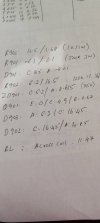
@p4spooky here is my note, i colored them to make my eyes easier to see. Sorry if the color make you dizzy,
Just focus to the red text
14.4 > 11.9

means 14.4 is start, after > 11.9 means after delay 5 secs.

2027.07.27_A.png

2027.07.27_B.png

Hope this help.
 
According to your numbers above - you have no voltage drop across the relay coil, even after Q901 turns on (D902 anode and cathode values are the same).
Have you replaced D902 yet ? if not, that's certainly one to try (in simulation, with D902 shorted, I see just under 8V at Q901(C))

To your other Q's:
- changing resistor values in the existing circuit is unlikely to resolve it
- a 5.1V Zener is not suitable as a replacement for ZD901, not even temporarily (but I think ZD901 is fine anyway)
 
@Goldie99 not yet, idont have much zener and diode onhand right now, already ordered the transistor, zener and elcos. Take 3-5 days to arrive since i live in remote area far from big city.
 
Maybe try just removing D902 and checking it on a meter - it should be a standard diode. If it's shorted it'll conduct in both directions.
Don't run the circuit without it though.
 
Guyssss!!! It Worksss!!

@Goldie99 you are right! After ordering zener and transistor, when thinking to following @p4spooky to replace all component in the muting area, i forget to order D804 1S2706A, and start panicking because the shipping is a bit high.

Then i found this thread:
https://audiokarma.org/forums/index...-zener-diode-subs-1s2076-and-1s2076a.1002985/
Any 1N4148 can replace them, and i found in my stock FairChild 1N4148, i put on D804, it is change abit, but i forget what voltage, then i try remove another one which is in D902, then i check the volteage, its drop! Check vac on the RCA output it is 1.5vac! I think its around 8 secs.

Will try them tonight and will update the voltage information.
 
Last edited:
Back
Top Bottom